48
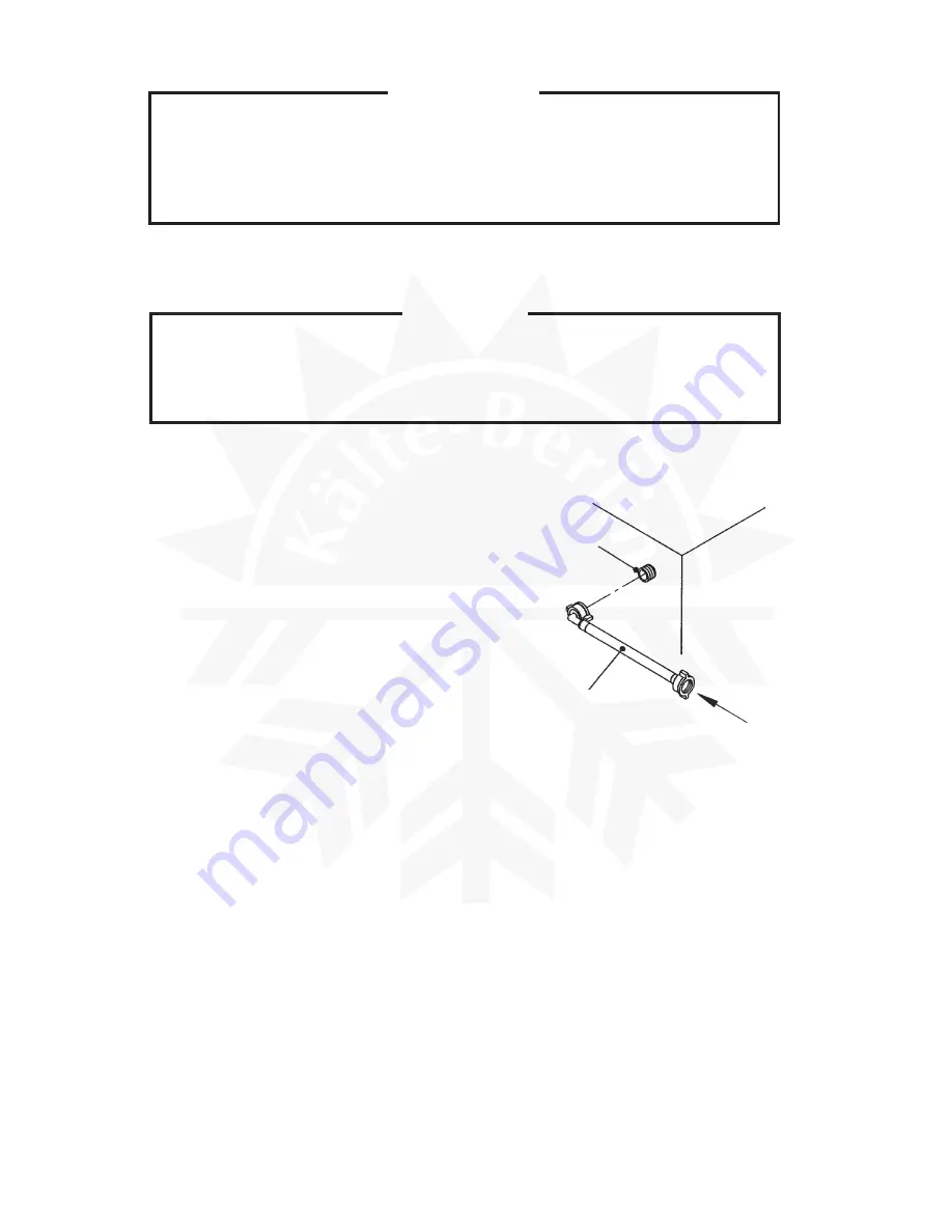
Fig. 12
Air or CO
2
Water
Inlet
Inlet Hose
IMPORTANT
1. Check the conditions and quality of the ice production.
2. Do not use ice produced in the trial run. It might be contaminated with foreign
matter in the water circuit. Discard or flush down the drain.
2. PREPARING THE ICEMAKER FOR LONG STORAGE
WARNING
Drain the icemaker to prevent damage to the water supply line at subfreezing
temperatures, using air or carbon dioxide. Shut off the icemaker until proper air
temperature is resumed.
[a] IM-21, IM-25, IM-30, IM-45, IM-65
1) Close the water supply tap, and remove the Inlet
Hose.
2) Remove the Front Panels (Upper and Lower).
3) Push the Reset Switch in the Control Box, or
disconnect power source and reconnect after
3 minutes.
4) The Water Pan will open, and then the Actuator
Toggle Switch will turn to the “DEFROST”
position in 40 seconds. (Click sound will be
heard.)
5) Blow out the water supply line immediately after
the Water Pan has opened.
Note: This procedure is necessary to protect the icemaker from freezing up at subfreezing
temperature.
6) Unplug the icemaker with the Actuator Toggle Switch in the “DEFROST” position.
7) Remove all ice from the Storage Bin, and clean the Bin.
8) Replace the panels in their correct positions.
9) Replace the Inlet Hose in its correct position.
Summary of Contents for IM-100
Page 5: ...1 I SPECIFICATIONS 1 DIMENSIONS CONNECTIONS a IM 25LE Air cooled ...
Page 6: ...2 b IM 25CLE Air cooled Until March 2000 production Auxiliary Code K 1 ...
Page 7: ...3 c IM 21CLE IM 25CLE IM 30CLE Air cooled From April 2000 production Auxiliary Code K 2 ...
Page 8: ...4 d IM 45LE Air cooled ...
Page 9: ...5 e IM 45CLE 25 Air cooled ...
Page 10: ...6 f IM 65LE Air cooled ...
Page 11: ...7 g IM 100LE IM 130LE IM 130ME Air cooled ...
Page 12: ...8 h IM 100CLE Air cooled ...
Page 13: ...9 i IM 160ME Air cooled ...
Page 14: ...10 j IM 240ME Air cooled ...
Page 15: ...11 k IM 240M2E Air cooled ...
Page 16: ...12 l IM 25WLE IM 30WLE Water cooled ...
Page 17: ...13 m IM 45WLE Water cooled ...
Page 18: ...14 n IM 65WLE Water cooled ...
Page 19: ...15 o IM 100WLE IM 130WLE IM 130WME Water cooled ...
Page 20: ...16 p IM 240WME Water cooled ...
Page 21: ...17 q IM 240WM2E Water cooled ...
Page 70: ...66 2 WIRING DIAGRAM a IM 21CLE IM 25LE IM 25CLE IM 30CLE IM 25WLE IM 30WLE ...
Page 71: ...67 b IM 25L IM 25CL IM 25WL ...
Page 72: ...68 c IM 45LE IM 45CLE 25 IM 45WLE ...
Page 73: ...69 d IM 65LE IM 65WLE ...
Page 74: ...70 e IM 65L IM 65WL ...
Page 76: ...72 g IM 130LE IM 130WLE Note The Washing Switch is provided only after the Auxiliary Code H 0 ...
Page 78: ...74 i IM 130ME IM 130WME Note The Washing Switch is provided only after the Auxiliary Code H 0 ...
Page 80: ...76 k IM 160ME ...
Page 81: ...77 l IM 240ME IM 240WME ...
Page 82: ...78 m IM 240M2E IM 240WM2E ...
Page 120: ...116 Fig 30 ...


