55
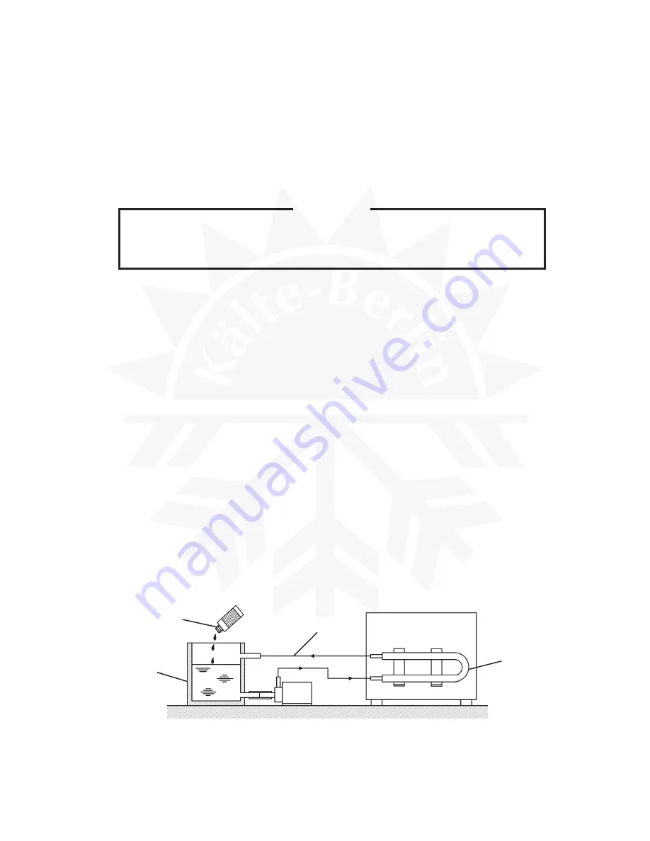
Fig. 18
Cleaner
Container
Hose
Condenser
3. WATER-COOLED CONDENSER
Deposits inside the water circuit of the Water-cooled Condenser decrease cooling
performance. Clean inside of the Condenser by circulating a cleaning solution.
1) Prepare the following:
Cleaning solution [Read and follow any instructions on label or bottle.]
Pump
Container for solution
Hose
Hose bands
Two fittings [R1/2 - 3/8”DIA]
Two fittings [3/8” flare - 3/8”DIA]
CAUTION
Do not use a cleaning solution that will corrode the copper tubing. In case of
contact with the solution, flush with water.
2) Remove the panels and check for leaks from the water line.
3) Unplug the icemaker or disconnect the power source, and close the water supply tap.
4) Disconnect the cooling water inlet and outlet pipings and attach fittings to connect hoses.
5) Disconnect the inlet and outlet tubings of the Water Regulator and replace the Water
Regulator by fittings.
6) Connect hoses as shown in Fig. 18 and secure them by hose bands.
7) Fill the container with the cleaning solution.
8) Run the pump motor and circulate the solution for a period recommended in the instructions
on label or bottle of the cleaner.
9) Rinse the water circuit.
10) Reverse the above procedure in steps 2) through 6).
11) Check the icemaking capacity referring to “VI. 3. PERFORMANCE DATA”.
Summary of Contents for IM-100
Page 5: ...1 I SPECIFICATIONS 1 DIMENSIONS CONNECTIONS a IM 25LE Air cooled ...
Page 6: ...2 b IM 25CLE Air cooled Until March 2000 production Auxiliary Code K 1 ...
Page 7: ...3 c IM 21CLE IM 25CLE IM 30CLE Air cooled From April 2000 production Auxiliary Code K 2 ...
Page 8: ...4 d IM 45LE Air cooled ...
Page 9: ...5 e IM 45CLE 25 Air cooled ...
Page 10: ...6 f IM 65LE Air cooled ...
Page 11: ...7 g IM 100LE IM 130LE IM 130ME Air cooled ...
Page 12: ...8 h IM 100CLE Air cooled ...
Page 13: ...9 i IM 160ME Air cooled ...
Page 14: ...10 j IM 240ME Air cooled ...
Page 15: ...11 k IM 240M2E Air cooled ...
Page 16: ...12 l IM 25WLE IM 30WLE Water cooled ...
Page 17: ...13 m IM 45WLE Water cooled ...
Page 18: ...14 n IM 65WLE Water cooled ...
Page 19: ...15 o IM 100WLE IM 130WLE IM 130WME Water cooled ...
Page 20: ...16 p IM 240WME Water cooled ...
Page 21: ...17 q IM 240WM2E Water cooled ...
Page 70: ...66 2 WIRING DIAGRAM a IM 21CLE IM 25LE IM 25CLE IM 30CLE IM 25WLE IM 30WLE ...
Page 71: ...67 b IM 25L IM 25CL IM 25WL ...
Page 72: ...68 c IM 45LE IM 45CLE 25 IM 45WLE ...
Page 73: ...69 d IM 65LE IM 65WLE ...
Page 74: ...70 e IM 65L IM 65WL ...
Page 76: ...72 g IM 130LE IM 130WLE Note The Washing Switch is provided only after the Auxiliary Code H 0 ...
Page 78: ...74 i IM 130ME IM 130WME Note The Washing Switch is provided only after the Auxiliary Code H 0 ...
Page 80: ...76 k IM 160ME ...
Page 81: ...77 l IM 240ME IM 240WME ...
Page 82: ...78 m IM 240M2E IM 240WM2E ...
Page 120: ...116 Fig 30 ...


