22
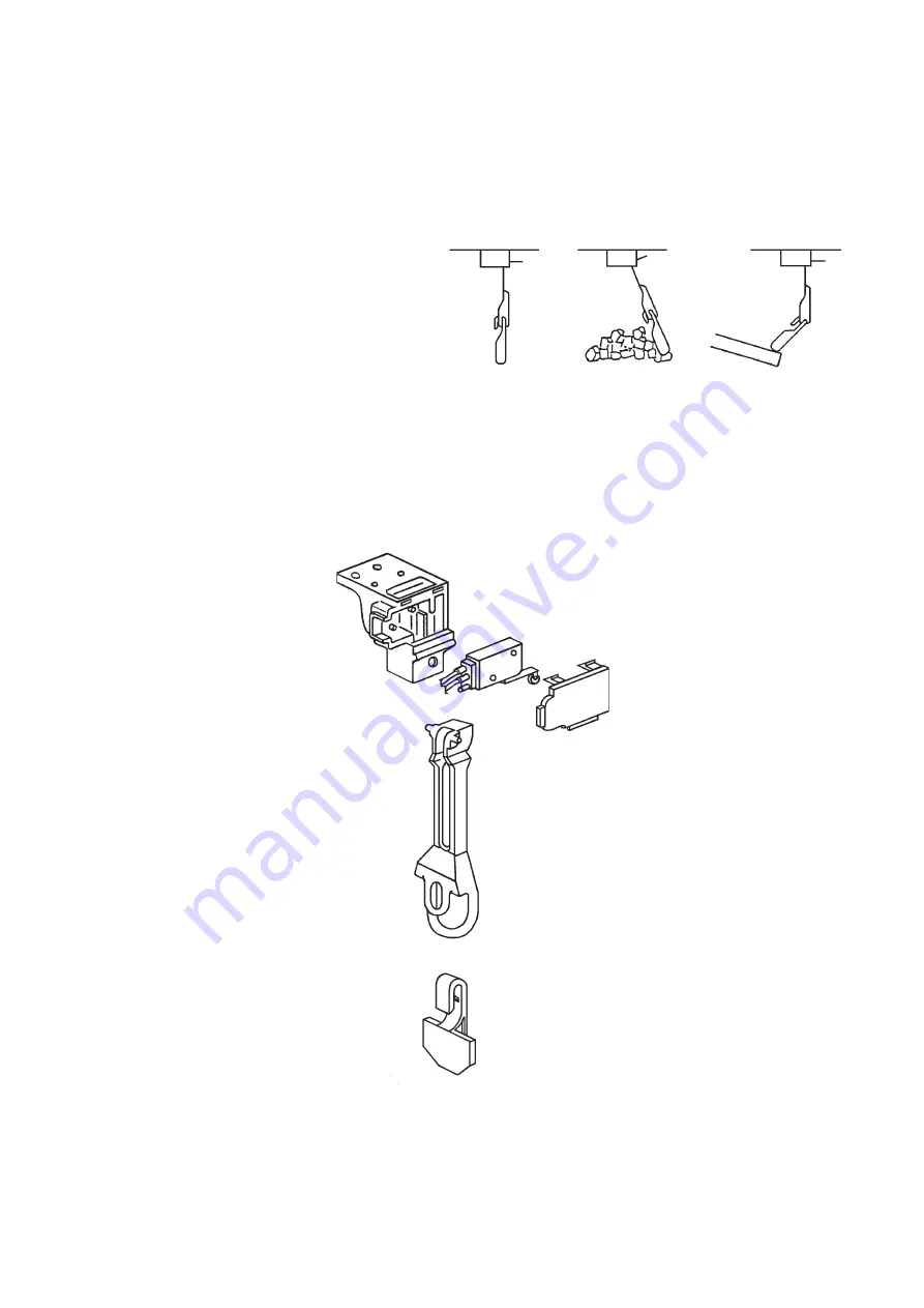
Fig. 2
Running
Bin full
Fragile
(Tripped)
Keep away from
water plate or
drain pan.
Fig. 3
Bracket
Microswitch
Switch
Bracket
Cover
Actuator
Detector
10) Replace the panels in their correct positions.
11) Replace the inlet hose in its correct position.
3. BIN CONTROL
Bin control switch is mounted on the
upper side of the storage bin. This switch
will turn off the unit automatically when
the storage bin is full of ice.
Handle the bin control switch carefully,
because the switch assembly is fragile.
Especially on removing ice, do not touch
or poke with a scoop.
Keep away from the water plate or drain
pan to prevent jamming.
[a] BIN CONTROL SWITCH ASSEMBLY
Summary of Contents for IM-240ANE
Page 4: ...1 I SPECIFICATIONS 1 DIMENSIONS SPECIFICATIONS a IM 240DNE Air cooled ...
Page 5: ...2 b IM 240DNE C Air cooled ...
Page 6: ...3 c IM 240DWNE Water cooled ...
Page 7: ...4 d IM 240DWNE C Water cooled ...
Page 8: ...5 e IM 240DWNE R452 Water cooled ...
Page 9: ...6 f IM 240ANE Air cooled ...
Page 10: ...7 g IM 240AWNE Water cooled ...
Page 11: ...8 h IM 240DSNE Remote Air cooled ...
Page 12: ...9 j URC 240C E 4 Condenser Unit ...
Page 20: ...17 a CONTROLLER BOARD LAYOUT Main Board Sub Board Combination ...
Page 37: ...34 2 WIRING DIAGRAM a IM 240DNE C XNE C IM 240DWNE C R452 XWNE C R452 IM 240ANE AWNE ...
Page 38: ...35 b IM 240DSNE XSNE URC 240C E 4 ...
Page 69: ...66 Fig 16 Controller Board Board Support Control Box Cover Screw ...


