47
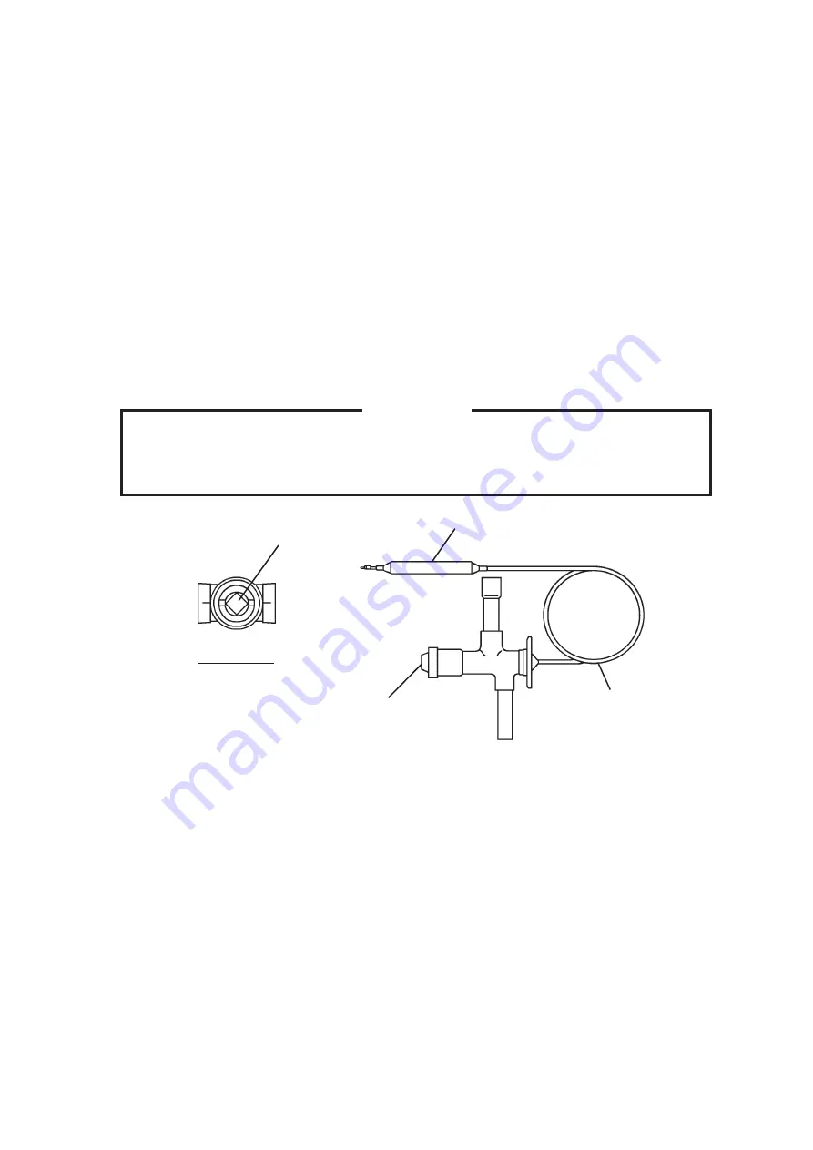
Fig. 8
Bottom View
Adjust Screw
Bulb
Capillary Tube
Cap Nut
Solder Connection
VII. ADJUSTMENT
1. EXPANSION VALVE
The expansion valve is factory-adjusted. Do not adjust it except at replacement or
service. Adjust the valve setting, if necessary, as follows:
1) Remove the cap nut.
2) Rotate the adjust screw by using a flat blade screwdriver.
3) Watch holes of ice cubes produced. Standard setting is that evaporator inlet side
and outlet side cubes have almost the same diameters. To make the inlet side larger,
rotate 90 - 180° clockwise. Smaller, counterclockwise. Do not rotate more than 180°
at a time.
CAUTION
Over adjustment of the valve may result in liquid refrigerant return causing
freezing to the suction line and severe damage to the compressor.
Summary of Contents for IM-240ANE
Page 4: ...1 I SPECIFICATIONS 1 DIMENSIONS SPECIFICATIONS a IM 240DNE Air cooled ...
Page 5: ...2 b IM 240DNE C Air cooled ...
Page 6: ...3 c IM 240DWNE Water cooled ...
Page 7: ...4 d IM 240DWNE C Water cooled ...
Page 8: ...5 e IM 240DWNE R452 Water cooled ...
Page 9: ...6 f IM 240ANE Air cooled ...
Page 10: ...7 g IM 240AWNE Water cooled ...
Page 11: ...8 h IM 240DSNE Remote Air cooled ...
Page 12: ...9 j URC 240C E 4 Condenser Unit ...
Page 20: ...17 a CONTROLLER BOARD LAYOUT Main Board Sub Board Combination ...
Page 37: ...34 2 WIRING DIAGRAM a IM 240DNE C XNE C IM 240DWNE C R452 XWNE C R452 IM 240ANE AWNE ...
Page 38: ...35 b IM 240DSNE XSNE URC 240C E 4 ...
Page 69: ...66 Fig 16 Controller Board Board Support Control Box Cover Screw ...


