48
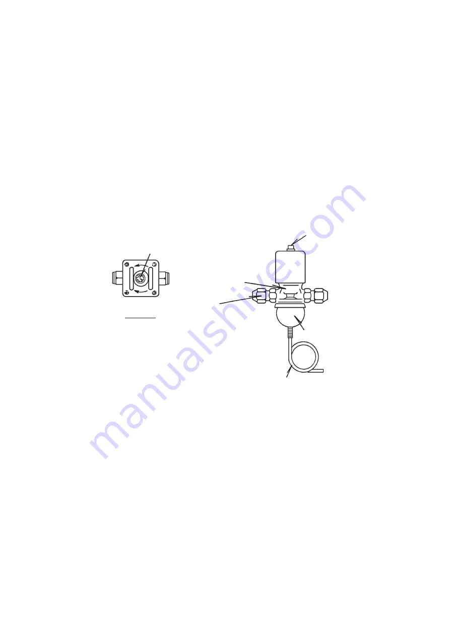
2. WATER REGULATING VALVE - WATER-COOLED MODEL ONLY
The water regulating valve is factory-adjusted. Do not adjust it except at replacement or
service. Adjust the valve setting, if necessary, as follows:
1) Attach a pressure gauge to high-side line, or prepare a thermometer to check
condenser drain temperature.
2) Rotate the adjust screw using a flat blade screwdriver so that the pressure gauge
shows 19 bar, or the thermometer reads 45 - 50°C, 5 minutes after freeze cycle
starts.
When the pressure or temperature exceeds the above, rotate the adjust screw
counterclockwise.
3) Check that the pressure or temperature holds.
Fig. 9
Top View
Adjust Screw
Flare
Connection
Capillary Tube
Bellows
Valve Body
Adjust Screw
Summary of Contents for IM-240ANE
Page 4: ...1 I SPECIFICATIONS 1 DIMENSIONS SPECIFICATIONS a IM 240DNE Air cooled ...
Page 5: ...2 b IM 240DNE C Air cooled ...
Page 6: ...3 c IM 240DWNE Water cooled ...
Page 7: ...4 d IM 240DWNE C Water cooled ...
Page 8: ...5 e IM 240DWNE R452 Water cooled ...
Page 9: ...6 f IM 240ANE Air cooled ...
Page 10: ...7 g IM 240AWNE Water cooled ...
Page 11: ...8 h IM 240DSNE Remote Air cooled ...
Page 12: ...9 j URC 240C E 4 Condenser Unit ...
Page 20: ...17 a CONTROLLER BOARD LAYOUT Main Board Sub Board Combination ...
Page 37: ...34 2 WIRING DIAGRAM a IM 240DNE C XNE C IM 240DWNE C R452 XWNE C R452 IM 240ANE AWNE ...
Page 38: ...35 b IM 240DSNE XSNE URC 240C E 4 ...
Page 69: ...66 Fig 16 Controller Board Board Support Control Box Cover Screw ...


