8
ENGLISH
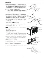
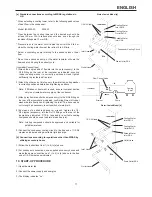
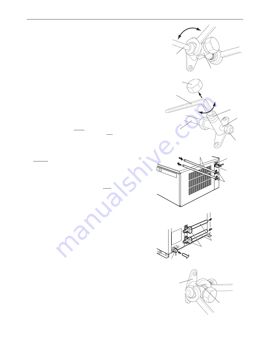
4) Connect the flared copper tubes on to the icemaker and condenser unit.
The two tubes have the same diameter so mark them for a distinction
between the gas line and the liquid line to prevent misconnection. Apply
some clean refrigerant oil of a suitable type to the surfaces of the flare
before connection and tightening. Support the access valve with a
spanner on the flat surfaces when tightening the nuts.
Note: 1. Tighten the flare nuts to a torque of 38±4 Nm.
2. Check the distinction marks on both ends of each copper tube to
make sure the connections are correct.
3. The tubes should not vibrate. Fix or secure the tubes to prevent
stressing.
5) Remove the service gauge port caps from the access valves on the
icemaker. Evacuate the lines through the gauge ports for 20 minutes
at max. 0.1 torr. Charge both lines with vapour refrigerant R404A
to a pressure of 1 bar. Add nitrogen to raise the pressure to 15 bar.
Thoroughly leak test the joints with a leak detector or soap bubbles.
6) Evacuate the lines again at max. 0.1 torr. Vapour charge the lines to 1 -
2 bar with refrigerant R404A. (The actual charge will depend upon the
length of tube run.)
Base charge up to 10m: 2000g
Additional charge for each additional meter: 40g
As the total precharged refrigerant amount in the icemaker and remote
condenser is 2000g, the required refrigerant charge will be:
40g x [length of tube run - 10] m
Example - If the length of tubing run is 15m (i.e. distance between the
icemaker and Condenser)
15m - 10m = 5m
Base charge = 2000g (up to 10m run)
Additional charge = 40g/m
Required refrigerant charge = 40g x 5m = 200g
On completion of the refrigerant charge, remove the charging cylinder
and charging lines. Refit the port caps and tighten to a torque of 10±1
Nm.
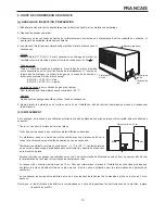
7) Remove the cap nuts from the access valves on both the condenser and
the icemaker. Open the liquid and gas line valves by turning the spindle
with a hexagon wrench until fully open.
8) Refit the cap nuts to a torque of 25±3 Nm.
9) Check the cap nuts, port caps and flare joints for gas leaks with a
detector or soap bubbles.
10) Insulate the joints and seal them for water tightness.
Note: When removing or installing the nuts on the access valves, hold the
flat surfaces of the valve with a spanner.
Liquid Line
Gas Line
Pipe Insulation
Fan Motor
Wiring Cord
Power Cord
Access Valve
Liquid Line
Gas Line
Pipe Insulation
Three-Wire Cord
Cord Grip
Access Valve
Loosen
Tighten
Copper Tube
Access Valve
Cap Nut
Open
Copper Tube
Hexagon
Wrench (H4)
Close
Spindle
Port
Port Cap
Flat Surface
Access Valve

