background image

68

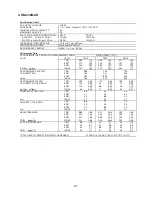
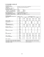
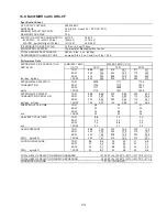
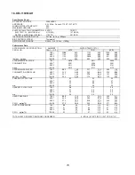
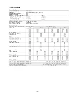
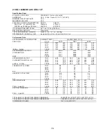
10. KM-650MWH

Specification Sheet

AC SUPPLY VOLTAGE

208-230/60/1 (3 wire with neutral) or 208-230/60/1

AMPERAGE

5.4 A (5 Min. Freeze AT 104°F/WT 80°F)

MINIMUM CIRCUIT AMPACITY

15 A

MAXIMUM FUSE SIZE

15 A

ELECTRIC & WATER CONSUMPTION 90/70°F

70/50°F

    ELECTRIC    W  (kWH/100 lbs.)

1130(4.16)

1120(4.03)

    WATER   gal./24HR (gal./100 lbs.)

145(22.3)

286(42.7)

    WATER COOLED CONDENSER

982(151)

503(75)


gal./24HR (gal./100 lbs.)

ICE PRODUCTION PER CYCLE

14.3  lbs. (6.5 kg) 720 pcs.

BIN CONTROL SYSTEM

Thermostat or Mechanical Bin Control

REFRIGERANT CHARGE

R-404A, 1 lb. 5.2 oz. (600g)

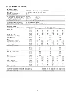
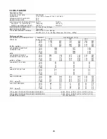
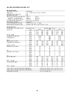
Performance Data

70/21

669

303

663

301

626

284

80/27

665

302

656

298

602

273

90/32

663

301

650

295

602

273

lbs./day   kg./day

100/38

646

293

639

290

557

253

70/21

80/27

90/32

watts

100/38

70/21

789

2.99

888

3.36

1449

5.49

80/27

864

3.27

1018

3.85

1816

6.88

90/32

888

3.36

1126

4.26

1836

6.95

gal./day    m3/day

100/38

1218

4.61

1293

4.89

2489

9.42

70/21

80/27

90/32

min.

100/38

70/21

80/27

90/32

min.

100/38

70/21

239

16.8

240

16.8

248

17.5

80/27

239

16.8

240

16.9

254

17.8

90/32

240

16.8

241

16.9

252

17.8

PSIG     kg/cm2G

100/38

244

17.2

244

17.1

263

18.5

70/21

50

3.5

50

3.5

53

3.7

80/27

50

3.5

51

3.6

54

3.8

90/32

50

3.5

51

3.6

54

3.8

PSIG     kg/cm2G

100/38

51

3.6

52

3.6

57

4.0

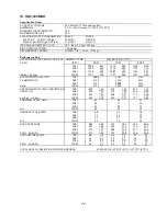
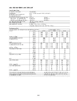
TOTAL HEAT OF REJECTION FROM COMPRESSOR

1,400 BTU/h  [AT 90ºF (32ºC) / WT 70ºF (21ºC)]

WATER FLOW FOR CONDENSER

99.6 gal./h  [AT 100ºF (38ºC) / WT 90ºF (32ºC)]

PRESSURE DROP OF COOLING WATER LINE

less than 10 PSIG

APPROXIMATE ELECTRIC 

CONSUMPTION

1120

1123

APPROXIMATE ICE PRODUCTION 

PER 24 HR.

AMBIENT TEMP. 

(ºF/ºC)

WATER TEMP. (ºF/ºC)

50/10

70/21

90/32

1139

1122

1127

1150

1123

1130

1151

1130

1135

1170

APPROXIMATE WATER 

CONSUMPTION PER 24 HR.

FREEZING CYCLE TIME

28

28

30

28

29

31

28

30

32

29

30

34

HARVEST CYCLE TIME

4.1

3.6

3.3

3.7

3.0

2.9

3.6

2.5

2.3

3.1

2.4

2.1

HEAD PRESSURE

SUCTION PRESSURE

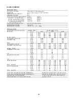
TOTAL HEAT OF REJECTION FROM CONDENSER

9,200 BTU/h  [AT 90ºF (32ºC) / WT 70ºF (21ºC)]

ENG.F-011.1.0205

Summary of Contents for KM-320MAH

Page 1: ...650MAH MWH MRH KM 901MAH MWH MRH 3 KM 1100MAH MWH MRH KM 1340MAH MWH MRH KM 1601MRH 3 Hoshizaki A Superior Degree of Reliability www hoshizaki com Models Modular Crescent Cuber Hoshizaki America Inc Number 73196 Issued 4 29 2013 Revised 3 2 2016 SERVICE MANUAL ...

Page 2: ...stallation is not covered under warranty Hoshizaki provides this manual primarily to assist qualified service technicians in the service of the appliance Should the reader have any questions or concerns which have not been satisfactorily addressed please call send an e mail message or write to the Hoshizaki Technical Support Department for assistance Phone 1 800 233 1940 770 487 2331 Fax 1 800 843...

Page 3: ...trol Check and Cleaning 32 E Float Switch Check and Cleaning 34 1 Float Switch Check 34 2 Float Switch Cleaning 35 F Thermistor Check 36 G Diagnostic Tables 37 III Controls and Adjustments 41 A Control Board Layout 42 1 E Control Board 42 2 G Control Board 43 B LED Lights and Audible Alarm Safeties 44 1 E Control Board 44 2 G Control Board 45 C Settings and Adjustments 46 1 Default Dip Switch Sett...

Page 4: ... 54 V Maintenance 55 VI Preparing the Appliance for Periods of Non Use 56 VII Disposal 58 VIII Technical Information 59 A Specification and Performance Data Sheets 59 1 KM 320MAH 59 2 KM 320MWH 60 3 KM 340MAH 61 4 KM 340MWH 62 5 KM 515MAH 63 6 KM 515MWH 64 7 KM 515MRH with URC 5F 65 8 KM 600MAH 66 9 KM 650MAH 67 10 KM 650MWH 68 11 KM 650MRH with URC 5F 69 12 KM 901MAH 70 13 KM 901MWH 71 14 KM 901M...

Page 5: ...RH C 0 and earlier 86 d KM 901MWH D 1 and later KM 901MRH C 1 and later 87 e KM 1340MAH KM 1340MWH 88 f KM 1340MRH 89 g KM 1601MRH 90 h KM 901MRH3 KM 1601MRH3 91 2 Diagrams With Harvest Pump Timer Relays 92 a KM 340M_H 92 b KM 515MAH 93 c KM 650MAH V 2 to C 2 KM 650MWH V 2 to C 2 KM 901MAH B 1 to C 2 94 d KM 650MAH D 1 and later KM 650MWH D 1 and later KM 901MAH D 1 and later 95 e KM 650MRH V 2 to...

Page 6: ...pplicable national state and local codes and regulations Electrical connection must be hard wired and must meet national state and local electrical code requirements Failure to meet these code requirements could result in death electric shock serious injury fire or severe damage to equipment The icemaker requires an independent power supply of proper capacity See the nameplate for electrical speci...

Page 7: ...he icemaker control switch to the OFF position and turn off the power supply to the icemaker before servicing the remote condenser unit Lockout Tagout to prevent the power supply from being turned back on inadvertently NOTICE Follow the instructions in this manual carefully to reduce the risk of costly water damage In areas where water damage is a concern install in a contained area with a floor d...

Page 8: ...y Inlet Condenser Drier Control Box Spray Tubes Control Switch Water Pump Float Switch Compressor Thermostatic Expansion Valve Fan Motor Hot Gas Valve Thermostatic Bin Control Bracket Bulb Holder Cleaning Valve Mechanical Bin Control and Bracket Model Shown KM 515MAH Inlet Water Valve Liquid Line Valve KM 515MAH High Pressure Switch ...

Page 9: ... Float Switch Compressor Thermostatic Expansion Valve Water Regulating Valve Hot Gas Valve Cleaning Valve Thermostatic Bin Control Thermostatic Bin Control Bracket Bulb Holder Mechanical Bin Control and Bracket Model Shown KM 515MWH Inlet Water Valve Liquid Line Valve KM 320MWH and KM 515MWH High Pressure Switch ...

Page 10: ... Box Spray Tubes Control Switch Water Pump Float Switch Compressor Thermostatic Expansion Valves Hot Gas Valve Liquid Line Valve Cleaning Valve Thermostatic Bin Control Thermostatic Bin Control Bracket Bulb Holder Mechanical Bin Control and Bracket Model Shown KM 901MRH Inlet Water Valve ...

Page 11: ...h Pressure Switch Strainer Fan Drier Condenser Evaporator Discharge Line Suction Line Water Pump Thermistor Spray Tubes Inlet Water Valve Freeze Pump Out Water Tank Refrigeration Circuit Water Circuit Heat Exchanger Liquid Line Valve KM 515MAH B Water Refrigeration Circuit Diagram 1 Air Cooled Models MAH ...

Page 12: ...igh Pressure Switch Strainer Drier Condenser Evaporator Discharge Line Suction Line Water Pump Thermistor Spray Tubes Inlet Water Valve Freeze Pump Out Water Tank Refrigeration Circuit Water Circuit Heat Exchanger Liquid Line Valve KM 320MWH and KM 515MWH 2 Water Cooled Models MWH Water Regulating Valve ...

Page 13: ...essure Switch Strainer Fan Drier Condenser Evaporator Discharge Line Suction Line Water Pump Thermistor Spray Tubes Inlet Water Valve Freeze Pump Out Water Tank Refrigeration Circuit Water Circuit Liquid Line Valve Receiver Access Valve Headmaster C P R 3 Remote Models MRH 3 Thermostatic Expansion Valve Heat Exchanger ...

Page 14: ... min Maximum harvest time 20 min FS check 1 to 3 min harvest timer in control S4 dip switch 1 2 E and G Control Board Without Harvest Pump Timer Operation Flow Chart 1 1 Minute Fill Cycle Cycle Steps 2 Harvest Cycle Thermistor in control 3 Freeze Cycle Minimum freeze time 5 min Maximum freeze time freeze timer setting S4 dip switch 9 10 FS in control 4 Pump Out Cycle Factory set for every 10th cyc...

Page 15: ...s de energized 3 Ice Level Lowered Icemaker starts at 1 1 Minute Fill Cycle MBC closed MBC actuator paddle disengaged Green BC CLOSED LED on Yellow BC OPEN LED off 1 Bin Full Within 10 sec after ice contacts TBC bulb icemaker shuts down Shutdown and Restart TBC Operation Ice contacts TBC bulb 2 Icemaker Off All components de energized 3 Ice Level Lowered No ice touching TBC bulb Icemaker starts at...

Page 16: ...r every 10th cycle except KM 515M_H S4 dip switch 5 6 Pump motor stops for 2 sec then reverses for 10 20 sec S4 dip switch 3 4 WV energized FS open Comp energized FM energized KM 1100 FMR energized HGV energized WV energized Thermistor temperature reaches 48 F 9 C 3 9 kΩ or less Harvest timer starts 1 to 3 min FS open Comp continues FM continues KM 1100 FMR continues FM energized except KM 1100 LL...

Page 17: ...nd adequate water supply Check CB using the steps in II C Control Board Check Check dip switch settings to assure that S4 dip switch 3 4 7 8 9 10 and S5 dip switch 1 through 5 G CB are in the factory default position S4 dip switch 1 2 5 6 are cleaning adjustments and the settings are flexible For factory default settings see III C 1 Default Dip Switch Settings Note When checking high voltage 115VA...

Page 18: ...resent on control switch 2 P check for 115VAC at HPS P to neutral W then HPS BK to neutral W If 115VAC is present at HPS P and not at HPS BK HPS is open See HPS Diagnosis below If 115VAC is present at HPS BK check for 10 5VAC at CB K2 1 red wire to CB K2 2 red wire If 10 5VAC is not present check that the cleaning valve is closed and the interlock switch is closed Next check CT continuity If open ...

Page 19: ...eads 3 9 kΩ from the thermistor and turns harvest termination over to the harvest timer S4 dip switch 1 2 The harvest timer has settings of 60 90 120 and 180 sec The pump out timer S4 dip switch 3 4 acts in place of the harvest timer during cycles with a pump out S4 dip switch 5 6 WV remains energized during harvest for a maximum of 6 min or the length of harvest whichever is shorter a Comp Diagno...

Page 20: ...passing LLV and FM energize TXV and HM operate correctly WRV opens Comp is efficient and refrigerant charge is correct See VIII A Specification Sheet and VIII B Performance Data b Comp and FMR Diagnosis If Comp and FMR de energize once freeze begins check that appliance has not shut off on HPS POWER OK LED off If so check 3 b HPS Diagnosis above If POWER OK LED is on check for 115VAC at CB K1 1 V ...

Page 21: ...0 to 15 pound swing is not present replace TXV g WRV Diagnosis WRV is factory set and generally no adjustment is required If WRV fails to open in freeze check for proper refrigerant pressures See VIII B Performance Data If refrigerant pressures are correct and WRV does not open adjust or replace as needed See IV C Water Regulating Valve Adjustment water cooled models h Freeze Termination Diagnosis...

Page 22: ...itch 5 6 is factory set and generally no adjustment is required However the pump out frequency control can be set to have a pump out occur every cycle or every 2 5 or 10 cycles For details see III C 4 Pump Out Frequency Control S4 dip switch 5 6 Pump Out Diagnosis In the freeze cycle before pump out see table above disconnect CB black K5 connector FS connector after 5 min of freeze Check that PM s...

Page 23: ...st be left in the factory default position or the appliance will not operate correctly On G control boards CB red K4 connector jumper 4A4883G01 must be in place Diagnosis See II D 1 Thermostatic Bin Control Check b Mechanical Bin Control See II D 2 Mechanical Bin Control Check and Cleaning Legend BC bin control CB control board Comp compressor CV check valve FM fan motor FMR fan motor remote FS fl...

Page 24: ... P to neutral W then HPS BK to neutral W If 115VAC is present at HPS P and not at HPS BK HPS is open See HPS Diagnosis below If 115VAC is present at HPS BK check for 10 5VAC at CB K2 1 red wire to CB K2 2 red wire If 10 5VAC is not present check that the cleaning valve is closed and the interlock switch is closed Next check CT continuity If open replace CT b HPS Diagnosis Check that the condenser ...

Page 25: ...4 dip switch 5 6 WV and X11 relay are energized during harvest for a maximum of 6 min or the length of harvest minus 50 sec whichever is shorter 50 sec before harvest terminates PM energizes See step 5b below a Comp Diagnosis Check that evaporator is warming If not confirm that Comp energizes If not check for 115VAC at CB K1 1 or 9 V to neutral W If 115VAC is not present check for 115VAC at CB K1 ...

Page 26: ...al 3 P and not on terminal 5 Y replace X10 relay If 115VAC is present on X10 relay terminal 7 Y and PM is not energized check for 115VAC at X10 relay terminal 4 R to neutral W and terminal 6 DBU to neutral W If 115VAC is present on terminal 6 DBU and not on terminal 4 R replace X10 relay If 115VAC is present on X10 relay terminal 4 R check control switch contact continuity between terminals 4 R an...

Page 27: ...ling check for an inefficient Comp See VIII B Performance Data If Comp is energized but FMR is not check for 115VAC at the FMR junction box If 115VAC is not present check icemaker wiring connections If 115VAC is present check for voltage at condenser unit If 115VAC is not present check field wiring connections If 115VAC is present check FMR capacitor motor winding and fan blade for binding c WV an...

Page 28: ...ote Normal freeze cycle will last 20 to 40 min depending on model and conditions Cycle times and pressures should follow performance data provided in this manual See VIII B Performance Data i Short Freeze Cycle Diagnosis Confirm water tank fills and overflows during 1 min fill and harvest cycles If not check water supply filters shut off valve WV screen If water tank empties before 5 min timer ter...

Page 29: ...nergized and X10 relay is energized replace X11 relay contacts sticking If X10 relay is de energized check for 115VAC at terminal 6 DBU to neutral W and terminal 2 DBU to neutral W If 115VAC is present on terminal 6 DBU and not on terminal 2 DBU replace X10 relay If PM is energized and rotating in pump out rotation make sure the drain line is not clogged and that CV is clean and operating properly...

Page 30: ...e and the red LED is off replace CB If the secondary circuit does not have proper voltage check CT primary circuit Check for 115VAC at CB K1 connector pin 10 BR to neutral W for 115VAC Always choose a white W neutral wire to establish a good neutral connection when checking voltages For additional checks see II G 1 No Ice Production 3 The OUTPUT TEST button provides a relay sequence test Make sure...

Page 31: ... conditions particularly at higher altitude locations Note On G control boards a jumper 4A4883G01 must be placed on CB red K4 connector Otherwise CB yellow BC OPEN LED is on and appliance will not start To check TBC follow the steps below 1 Turn off the power supply 2 Remove the front panel then move the control switch to the OFF position 3 Remove the control box cover then clear any ice away from...

Page 32: ... actuator paddle is engaged MBC switch is open If closed check that the actuator paddle is not restricted Clean if necessary See II D 2 b Mechanical Bin Control Cleaning If MBC switch still reads closed replace MBC 8 Reconnect MBC connector to CB K4 connector then move the control switch to the ICE position Turn on the power supply 9 Check that CB green BC CLOSED LED is on 10 Allow the icemaker to...

Page 33: ...re of 1 part of Hoshizaki Scale Away and 25 parts of warm water Rinse the parts thoroughly with clean water 7 Reassemble MBC and replace it in its correct position Note If the magnet was removed for cleaning be sure to replace it in its correct position 8 Reconnect MBC connector to CB K4 connector then move the control switch to the ICE position 9 Replace the control box cover in its correct posit...

Page 34: ...ipe and the rubber cap in their correct positions Note Be sure the overflow pipe o ring is in its correct position on the overflow pipe 4 Remove the control box cover 5 Disconnect FS connector from CB K5 connector 6 Check for continuity across FS leads With the water tank empty FS should be open If open continue to step 7 If closed follow the steps in II E 2 Float Switch Cleaning After cleaning FS...

Page 35: ...vering the overflow pipe in the water tank Remove the overflow pipe by turning it counterclockwise After the water tank has drained replace the overflow pipe and the rubber cap in their correct positions Note Be sure the overflow pipe o ring is in its correct position on the overflow pipe 4 Disconnect the vent tube and the flush tube from the top of FS then remove FS assembly and remove the rubber...

Page 36: ... range replace the thermistor See IV B Component Service Information If within the normal range continue to the next step 7 Replace the thermistor in its correct position See IV B Component Service Information 8 Reconnect the thermistor connector to CB K3 connector 9 Replace the control box cover in its correct position 10 Move the control switch to the ICE position 11 Replace the front panel in i...

Page 37: ...frigerant lines or components plugged 7 Control Transformer 115VAC 10 5VAC a Coil winding open or shorted 8 Control Board See II C Control Board Check a In alarm b Yellow BC OPEN LED on bin full G control board c Defective 9 Mechanical Bin Control See II D Bin Control Check a Tripped with bin filled with ice b Actuator does not move freely c Defective 10 Water Supply a Water supply off or improper...

Page 38: ...ist See the Hoshizaki America Technician s Pocket Guide or contact your local distributor for a copy of the freeze up checklist Freeze Up Possible Cause Harvest Cycle 1 Evaporator a Scaled up b Damaged 2 Cube Guides a Out of position b Damaged 3 Spray Tubes and or Spray Guides a Dirty b Out of position 4 Water Supply a Low water pressure b External water filters clogged c Insufficient water line s...

Page 39: ... Cleaning a Float does not move freely b Defective 7 Pump Motor a RPM too slow b Impeller damaged 8 Thermostatic Expansion Valve a Bulb loose or defective 9 Liquid Line Valve a Restricted 10 Headmaster C P R remote models a Not bypassing 3 Low Ice Production Low Ice Production Possible Cause Long Harvest Cycle 1 Evaporator a Scaled up 2 Spray Tubes and or Spray Guides a Dirty b Out of position 3 R...

Page 40: ...eck and Cleaning a Scaled up dirty b Float sticking c Defective switch 3 Inlet Water Valve a Leaking by 4 Hot Gas Valve a Erratic or open 5 Condenser a Clogged 6 Control Board See II C Control Board Check a Float switch connection loose K5 b Defective 7 Refrigerant Charge a Low 8 Thermostatic Expansion Valve a Bulb loose b Defective 9 Compressor a Inefficient or off 10 Pump Motor a RPM too slow 11...

Page 41: ...discharge It is especially important to touch the metal part of the icemaker when handling or replacing the control board Do not touch the electronic devices on the control board or the back of the control board Do not change wiring and connections Do not misconnect K3 WHITE K4 RED and K5 BLACK because the same connector is used for the thermistor mechanical bin control and float switch K4 RED is ...

Page 42: ...anual Freeze Timer LED yellow Harvest Backup Timer LED orange K2 Connector Control Transformer 10 5VAC ALARM RESET Button S4 Dip Switch OUTPUT TEST Button used to test relays on control board K3 white Connector Thermistor harvest control and high temperature safety K4 red Connector Open K5 black Connector Float Switch water level LED 1 X1 Relay K1 Connector Pin 1 9 LED 4 X4 Relay K1 Connector Pin ...

Page 43: ...d LED green on continuously in thermostatic bin control application LED 2 X2 Relay LED 2 on K1 Connector Pin 2 LED 2 off K1 Connector Pin 3 LED 3 X3 Relay LED 3 on K1 Connector Pin 5 LED 3 off K1 Connector Pin 4 energized in freeze LED 4 X4 Relay K1 Connector Pin 6 LED 1 X1 Relay K1 Connector Pin 1 9 K2 Connector Control Transformer 10 5VAC S5 Dip Switch ALARM RESET Button S4 Dip Switch OUTPUT TES...

Page 44: ...s every 3 sec Type of Alarm Notes 1 High Evaporator Temp temperature 127 F 53 C Check for harvest problem stuck HGV or relay hot water entering icemaker or shorted thermistor 2 Harvest Backup Timer harvest 20 min for two cycles in a row Orange H TIMER LED on Check for open thermistor HGV not opening TXV or LLV leaking by low charge or inefficient Comp or WRV leaking by 3 Freeze Timer freeze specif...

Page 45: ...own the icemaker and have alarms as listed below No of Beeps every 3 sec Type of Alarm Notes 1 High Evaporator Temp temperature 127 F 53 C Check for harvest problem stuck HGV or relay hot water entering icemaker or shorted thermistor 2 Harvest Backup Timer harvest 20 min for two cycles in a row Check for open thermistor HGV not opening TXV or LLV leaking by low charge or inefficient Comp or WRV le...

Page 46: ... OFF ON ON ON OFF OFF OFF KM 1340MAH OFF OFF ON ON ON ON OFF OFF OFF OFF KM 1340MWH KM 1601MRH 3 OFF OFF ON OFF ON ON OFF OFF OFF ON KM 1340MRH OFF OFF ON OFF ON ON OFF OFF OFF OFF b G Control Board with Harvest Pump Timer Operation S4 Dip Switch No 1 2 3 4 5 6 7 8 9 10 KM 340MAH KM 340MWH OFF OFF ON OFF ON ON ON OFF ON OFF KM 515MAH OFF OFF OFF OFF ON ON ON OFF ON OFF KM 650MAH KM 650MRH ON OFF O...

Page 47: ...arvest pump timer operation never adjust the pump out timer s harvest timer T2 for a time less than 150 sec Otherwise the icemaker will not perform properly On models with harvest pump timer do not adjust 3 off and 4 on Pump does not run in pump out rotation in this setting When a pump out is called for the pump motor stops for 2 sec then energizes in the reverse direction taking water from the bo...

Page 48: ...e first freeze cycle On G control boards the first pump out is dependent on S4 dip switch 5 6 See the table below E G Control Board 1st Pump Out S4 Dip Switch Setting Pump Out Frequency E Control Board G Control Board No 5 No 6 OFF OFF Every cycle After 1st freeze cycle After 2nd freeze cycle ON OFF Every 2 cycles After 3rd freeze cycle OFF ON Every 5 cycles After 6th freeze cycle ON ON Every 10 c...

Page 49: ...through the latching circuit Next LED 3 turns on and control board K1 connector pin 5 DBU wire energizes energizing the pump motor for the last 50 sec of harvest G Control Board S4 Dip Switch Setting Pump Motor Time sec No 7 ON 50 OFF 0 6 Factory Use S4 dip switch 8 Factory set for proper operation Do not adjust This must be left in the factory default position 7 Freeze Timer S4 dip switch 9 10 NO...

Page 50: ...not operate correctly 9 Refill Counter S5 dip switch 2 through 5 G Control Board NOTICE Do not adjust These must be left in the factory default position or the icemaker will not operate correctly D Control Switch The control switch has three positions OFF for power off ICE for icemaking and WASH to energize the pump motor when cleaning and sanitizing ...

Page 51: ...tem if using an electronic leak detector and then raise the pressure using nitrogen gas 140 PSIG Do not use R 404A as a mixture with pressurized air for leak testing NOTICE Always recover the refrigerant and store it in an approved container Do not discharge the refrigerant into the atmosphere Do not leave the system open for longer than 15 min when replacing or servicing parts The Polyol Ester PO...

Page 52: ... the new drier with the arrow on the drier in the direction of the refrigerant flow When brazing protect the drier by using a wet cloth to prevent the drier from overheating Do not allow the drier to exceed 250 F 121 C 2 Use an electronic leak detector or soap bubbles to check for leaks Add a trace of refrigerant to the system if using an electronic leak detector and then raise the pressure using ...

Page 53: ...inder on the scales if the service cylinder is not equipped with a dip tube invert the service cylinder then place it on the scales Open the high side valve on the gauge manifold 7 Allow the system to charge with liquid until the proper charge weight is met 8 If necessary add any remaining charge to the system through the low side NOTICE To prevent compressor damage use a throttling valve or liqui...

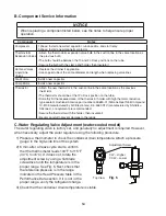
Page 54: ...hermal conductive type sealant Hoshizaki America part number 4A0683 01 Silicone Heat Sink Compound 10 8108 manufactured by GC Electronics KE 4560 RTV manufactured by ShinEtsu Silicones or equivalent are recommended Secure the thermistor with the holder then insulate it Be very careful to prevent damage to the leads C Water Regulating Valve Adjustment water cooled model The water regulating valve i...

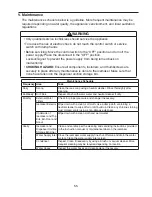
Page 55: ...scoop using a neutral cleaner Rinse thoroughly after cleaning Bi Weekly Air Filters Inspect Wash with warm water and neutral cleaner if dirty Monthly External Water Filters Check for proper pressure and change if necessary Icemaker Exterior Wipe down with a clean soft cloth Use a damp cloth containing a neutral cleaner to wipe off oil or dirt build up Clean any chlorine staining rust colored spots...

Page 56: ...ned off the power supply Make sure the control switch is in the ICE position Replace the front panel in its correct position then turn on the power supply 6 Blow the icemaker water supply line out using the compressed air or carbon dioxide supply 7 Close the icemaker water supply line drain valve 2 Remove the water from the water tank 1 Turn off the power supply then remove the front panel 2 Move ...

Page 57: ...ondenser return line shut off valve 3 Open the condenser water supply line drain valve If connected to a closed loop system also open the condenser return line drain valve 4 Attach a compressed air or carbon dioxide supply to the condenser water supply line drain valve 5 Open the water regulating valve by using a screwdriver to pry up on the spring retainer underneath the spring While holding the ...

Page 58: ...posal The appliance contains refrigerant and must be disposed of in accordance with applicable national state and local codes and regulations Refrigerant must be recovered by properly certified service personnel ...

Page 59: ...218 99 lbs day kg day 100 38 286 130 240 109 193 88 70 21 80 27 90 32 watts 100 38 70 21 173 0 65 145 0 55 126 0 48 80 27 151 0 57 108 0 41 100 0 38 90 32 145 0 55 77 0 29 64 0 24 gal day m3 day 100 38 111 0 42 74 0 28 53 0 20 70 21 80 27 90 32 min 100 38 70 21 80 27 90 32 min 100 38 70 21 237 16 7 256 18 0 279 19 6 80 27 251 17 7 280 19 7 302 21 2 90 32 256 18 0 301 21 2 323 22 7 PSIG kg cm2 G 10...

Page 60: ... 88 518 1 96 982 3 72 70 21 80 27 90 32 min 100 38 70 21 80 27 90 32 min 100 38 70 21 269 18 9 270 19 0 273 19 2 80 27 270 19 0 272 19 1 276 19 4 90 32 270 19 0 273 19 2 277 19 5 PSIG kg cm 2 G 100 38 271 19 1 274 19 3 280 19 7 70 21 56 3 9 57 4 0 58 4 1 80 27 57 4 0 59 4 1 59 4 2 90 32 57 4 0 61 4 3 61 4 3 PSIG kg cm 2 G 100 38 57 4 0 61 4 3 62 4 3 TOTAL HEAT OF REJECTION FROM COMPRESSOR 1 000 BT...

Page 61: ... 90 32 127 0 48 65 0 25 46 0 18 gal day m 3 day 100 38 94 0 36 61 0 23 29 0 11 70 21 80 27 90 32 min 100 38 70 21 80 27 90 32 min 100 38 70 21 220 15 5 241 16 9 259 18 2 80 27 236 16 6 268 18 8 280 19 7 90 32 241 16 9 290 20 4 306 21 5 PSIG kg cm 2 G 100 38 241 16 9 294 20 6 320 22 5 70 21 50 3 5 53 3 7 56 3 9 80 27 52 3 7 57 4 0 59 4 2 90 32 53 3 7 60 4 2 63 4 4 PSIG kg cm2 G 100 38 53 3 7 61 4 3...

Page 62: ...0 32 min 100 38 70 21 264 18 6 264 18 6 267 18 8 80 27 264 18 6 265 18 6 268 18 9 90 32 264 18 6 265 18 6 268 18 9 PSIG kg cm2G 100 38 265 18 7 266 18 7 271 19 1 70 21 57 4 0 58 4 0 61 4 3 80 27 57 4 0 58 4 1 63 4 4 90 32 58 4 0 59 4 1 63 4 4 PSIG kg cm2G 100 38 59 4 2 60 4 2 67 4 7 7 500 BTU h AT 90ºF 32ºC WT 70ºF 21ºC TOTAL HEAT OF REJECTION FROM COMPRESSOR 1 000 BTU h AT 90ºF 32ºC WT 70ºF 21ºC ...

Page 63: ...0 51 90 32 188 0 71 83 0 32 76 0 29 gal day m3 day 100 38 140 0 53 82 0 31 69 0 26 70 21 80 27 90 32 min 100 38 70 21 80 27 90 32 min 100 38 70 21 234 16 5 257 18 1 285 20 0 80 27 252 17 7 288 20 2 313 22 0 90 32 257 18 1 313 22 0 340 23 9 PSIG kg cm2 G 100 38 261 18 4 319 22 4 364 25 6 70 21 47 3 3 50 3 5 56 3 9 80 27 49 3 5 54 3 8 61 4 3 90 32 50 3 5 58 4 1 64 4 5 PSIG kg cm2 G 100 38 52 3 6 59 ...

Page 64: ...2 35 648 2 45 1173 4 44 70 21 80 27 90 32 min 100 38 70 21 80 27 90 32 min 100 38 70 21 266 18 7 267 18 8 270 19 0 80 27 267 18 7 268 18 8 272 19 1 90 32 267 18 8 269 18 9 273 19 2 PSIG kg cm2G 100 38 268 18 8 270 19 0 276 19 4 70 21 48 3 4 50 3 5 55 3 9 80 27 49 3 5 52 3 7 59 4 1 90 32 50 3 5 54 3 8 60 4 2 PSIG kg cm2G 100 38 52 3 6 55 3 9 66 4 6 8 200 BTU h AT 90ºF 32ºC WT 70ºF 21ºC TOTAL HEAT O...

Page 65: ... 168 0 64 94 0 36 88 0 33 gal day m3 day 100 38 133 0 50 93 0 35 82 0 31 70 21 80 27 90 32 min 100 38 70 21 80 27 90 32 min 100 38 70 21 216 15 2 234 16 4 252 17 7 80 27 230 16 1 257 18 1 272 19 1 90 32 234 16 4 277 19 5 294 20 6 PSIG kg cm2G 100 38 235 16 6 281 19 8 309 21 7 70 21 47 3 3 50 3 5 52 3 6 80 27 49 3 5 54 3 8 54 3 8 90 32 50 3 5 57 4 0 58 4 1 PSIG kg cm2G 100 38 50 3 5 57 4 0 59 4 1 8...

Page 66: ...54 0 58 90 32 212 0 80 99 0 38 92 0 35 gal day m3 day 100 38 160 0 61 97 0 37 85 0 32 70 21 80 27 90 32 min 100 38 70 21 80 27 90 32 min 100 38 70 21 238 16 7 259 18 2 290 20 4 80 27 254 17 9 287 20 2 319 22 4 90 32 259 18 2 310 21 8 342 24 1 PSIG kg cm2G 100 38 266 18 7 318 22 3 372 26 2 70 21 55 3 9 56 4 0 58 4 1 80 27 56 3 9 58 4 0 60 4 2 90 32 56 4 0 59 4 1 61 4 3 PSIG kg cm2G 100 38 57 4 0 59...

Page 67: ...03 0 77 143 0 54 139 0 53 90 32 194 0 73 101 0 38 89 0 34 gal day m3 day 100 38 149 0 56 98 0 37 78 0 30 70 21 80 27 90 32 min 100 38 70 21 80 27 90 32 min 100 38 70 21 232 16 3 252 17 8 280 19 7 80 27 248 17 4 280 19 7 307 21 6 90 32 252 17 8 302 21 3 331 23 2 PSIG kg cm2G 100 38 258 18 1 309 21 7 357 25 1 70 21 50 3 5 52 3 7 55 3 9 80 27 52 3 6 56 3 9 58 4 1 90 32 52 3 7 58 4 1 61 4 3 PSIG kg cm...

Page 68: ...m3 day 100 38 1218 4 61 1293 4 89 2489 9 42 70 21 80 27 90 32 min 100 38 70 21 80 27 90 32 min 100 38 70 21 239 16 8 240 16 8 248 17 5 80 27 239 16 8 240 16 9 254 17 8 90 32 240 16 8 241 16 9 252 17 8 PSIG kg cm2G 100 38 244 17 2 244 17 1 263 18 5 70 21 50 3 5 50 3 5 53 3 7 80 27 50 3 5 51 3 6 54 3 8 90 32 50 3 5 51 3 6 54 3 8 PSIG kg cm2G 100 38 51 3 6 52 3 6 57 4 0 TOTAL HEAT OF REJECTION FROM C...

Page 69: ...228 0 86 149 0 56 155 0 59 90 32 216 0 82 93 0 35 88 0 33 gal day m3 day 100 38 160 0 61 92 0 35 82 0 31 70 21 80 27 90 32 min 100 38 70 21 80 27 90 32 min 100 38 70 21 211 14 9 231 16 3 253 17 8 80 27 227 15 9 258 18 1 277 19 5 90 32 231 16 3 280 19 7 301 21 1 PSIG kg cm2G 100 38 234 16 5 285 20 0 320 22 5 70 21 51 3 6 53 3 7 56 3 9 80 27 52 3 7 55 3 8 58 4 1 90 32 53 3 7 56 3 9 59 4 2 PSIG kg cm...

Page 70: ...6 0 97 182 0 69 172 0 65 90 32 244 0 92 130 0 49 111 0 42 gal day m3 day 100 38 188 0 71 126 0 48 94 0 36 70 21 80 27 90 32 min 100 38 70 21 80 27 90 32 min 100 38 70 21 217 15 3 235 16 6 261 18 4 80 27 231 16 2 260 18 3 286 20 1 90 32 235 16 6 280 19 7 307 21 6 PSIG kg cm2G 100 38 241 16 9 286 20 1 331 23 3 70 21 36 2 5 38 2 7 42 2 9 80 27 37 2 6 40 2 8 45 3 2 90 32 38 2 7 42 3 0 47 3 3 PSIG kg c...

Page 71: ...3 day 100 38 1298 4 91 1422 5 38 2403 9 09 70 21 80 27 90 32 min 100 38 70 21 80 27 90 32 min 100 38 70 21 239 16 8 240 16 9 248 17 5 80 27 240 16 9 242 17 0 254 17 8 90 32 240 16 9 243 17 1 253 17 8 PSIG kg cm2G 100 38 244 17 2 245 17 3 263 18 5 70 21 34 2 4 35 2 5 37 2 6 80 27 35 2 4 36 2 5 38 2 7 90 32 35 2 5 37 2 6 39 2 7 PSIG kg cm2G 100 38 35 2 5 37 2 6 41 2 9 10 100 BTU h AT 90ºF 32ºC WT 70...

Page 72: ...9 165 0 63 90 32 219 0 83 152 0 57 131 0 50 gal day m3 day 100 38 182 0 69 147 0 56 112 0 42 70 21 80 27 90 32 min 100 38 70 21 80 27 90 32 min 100 38 70 21 208 14 6 229 16 1 252 17 7 80 27 224 15 7 256 18 0 277 19 5 90 32 229 16 1 279 19 6 301 21 2 PSIG kg cm2G 100 38 232 16 3 284 20 0 322 22 6 70 21 35 2 5 37 2 6 41 2 9 80 27 37 2 6 40 2 8 45 3 1 90 32 37 2 6 43 3 0 47 3 3 PSIG kg cm2G 100 38 38...

Page 73: ...22 0 84 147 0 56 134 0 51 gal day m3 day 100 38 185 0 70 144 0 54 123 0 46 70 21 80 27 90 32 min 100 38 70 21 80 27 90 32 min 100 38 70 21 206 14 5 225 15 8 248 17 5 80 27 220 15 5 249 17 5 272 19 1 90 32 225 15 8 270 19 0 293 20 6 PSIG kg cm2G 100 38 229 16 1 275 19 4 315 22 1 70 21 36 2 5 38 2 7 41 2 9 80 27 37 2 6 40 2 8 44 3 1 90 32 38 2 7 42 3 0 46 3 2 PSIG kg cm2G 100 38 39 2 7 43 3 0 49 3 4...

Page 74: ... 32 327 1 24 175 0 66 153 0 58 gal day m 3 day 100 38 253 0 96 170 0 64 132 0 50 70 21 80 27 90 32 min 100 38 70 21 80 27 90 32 min 100 38 70 21 255 17 9 274 19 2 300 21 1 80 27 269 18 9 298 21 0 325 22 9 90 32 274 19 2 319 22 4 346 24 3 PSIG kg cm 2 G 100 38 279 19 6 325 22 9 371 26 1 70 21 50 3 5 52 3 6 55 3 8 80 27 51 3 6 54 3 8 57 4 0 90 32 52 3 6 56 3 9 59 4 2 PSIG kg cm2 G 100 38 53 3 7 57 4...

Page 75: ... 6 27 2462 9 32 70 21 80 27 90 32 min 100 38 70 21 80 27 90 32 min 100 38 70 21 234 16 5 236 16 6 246 17 3 80 27 236 16 6 239 16 8 253 17 8 90 32 236 16 6 241 16 9 254 17 9 PSIG kg cm2 G 100 38 241 16 9 244 17 2 266 18 7 70 21 51 3 6 51 3 6 54 3 8 80 27 51 3 6 51 3 6 55 3 9 90 32 51 3 6 51 3 6 55 3 8 PSIG kg cm2 G 100 38 52 3 7 52 3 6 58 4 1 TOTAL HEAT OF REJECTION FROM CONDENSER 17900 BTU h AT 90...

Page 76: ... 1 14 168 0 64 150 0 57 gal day m 3 day 100 38 236 0 89 164 0 62 133 0 50 FREEZING CYCLE TIME 70 21 80 27 90 32 min 100 38 HARVEST CYCLE TIME 70 21 80 27 90 32 min 100 38 HEAD PRESSURE 70 21 208 14 6 224 15 8 244 17 2 80 27 221 15 5 246 17 3 264 18 6 90 32 224 15 8 264 18 6 283 19 9 PSIG kg cm 2 G 100 38 227 16 0 269 18 9 301 21 2 SUCTION PRESSURE 70 21 49 3 4 51 3 6 55 3 9 80 27 51 3 6 54 3 8 58 ...

Page 77: ...05 246 0 93 90 32 355 1 34 214 0 81 174 0 66 gal day m3 day 100 38 280 1 06 204 0 77 137 0 52 70 21 80 27 90 32 min 100 38 70 21 80 27 90 32 min 100 38 70 21 251 17 6 272 19 1 293 20 6 80 27 267 18 8 299 21 0 316 22 2 90 32 272 19 1 322 22 6 341 24 0 PSIG kg cm2G 100 38 274 19 2 327 23 0 359 25 2 70 21 45 3 2 48 3 4 50 3 5 80 27 48 3 4 52 3 7 53 3 7 90 32 48 3 4 56 3 9 57 4 0 PSIG kg cm2G 100 38 4...

Page 78: ...8 1910 7 23 2079 7 87 2905 11 00 70 21 80 27 90 32 min 100 38 70 21 80 27 90 32 min 100 38 70 21 234 16 5 236 16 6 249 17 5 80 27 236 16 6 239 16 8 258 18 1 90 32 236 16 6 242 17 0 258 18 1 PSIG kg cm2G 100 38 242 17 0 245 17 3 273 19 2 70 21 45 3 2 46 3 2 48 3 4 80 27 46 3 2 47 3 3 50 3 5 90 32 46 3 2 48 3 4 51 3 6 PSIG kg cm2G 100 38 47 3 3 49 3 5 53 3 8 TOTAL HEAT OF REJECTION FROM COMPRESSOR W...

Page 79: ... 90 32 386 1 46 229 0 87 201 0 76 gal day m3 day 100 38 308 1 16 222 0 84 175 0 66 70 21 80 27 90 32 min 100 38 70 21 80 27 90 32 min 100 38 70 21 208 14 6 226 15 9 247 17 4 80 27 221 15 6 250 17 6 269 18 9 90 32 226 15 9 270 19 0 290 20 4 PSIG kg cm2G 100 38 229 16 1 275 19 3 309 21 7 70 21 44 3 1 47 3 3 49 3 4 80 27 46 3 2 50 3 5 51 3 6 90 32 47 3 3 53 3 7 54 3 8 PSIG kg cm2G 100 38 47 3 3 53 3 ...

Page 80: ... 12 90 32 418 1 58 263 1 00 217 0 82 gal day m3 day 100 38 335 1 27 252 0 95 174 0 66 70 21 80 27 90 32 min 100 38 70 21 80 27 90 32 min 100 38 70 21 200 14 1 215 15 1 231 16 3 80 27 211 14 9 234 16 5 249 17 5 90 32 215 15 1 251 17 6 266 18 7 PSIG kg cm2G 100 38 217 15 3 254 17 9 281 19 8 70 21 35 2 5 37 2 6 39 2 7 80 27 36 2 6 39 2 7 41 2 9 90 32 37 2 6 41 2 9 43 3 0 PSIG kg cm2G 100 38 37 2 6 41...

Page 81: ... 1 69 264 1 00 230 0 87 gal day m 3 day 100 38 355 1 34 256 0 97 200 0 76 70 21 80 27 90 32 min 100 38 70 21 80 27 90 32 min 100 38 70 21 205 14 4 218 15 3 233 16 4 80 27 215 15 1 236 16 6 249 17 5 90 32 218 15 3 250 17 6 265 18 6 PSIG kg cm 2 G 100 38 220 15 5 254 17 8 279 19 6 70 21 38 2 7 40 2 8 42 3 0 80 27 39 2 8 42 2 9 44 3 1 90 32 40 2 8 43 3 1 46 3 2 PSIG kg cm2 G 100 38 40 2 8 44 3 1 48 3...

Page 82: ...426 1 61 267 1 01 218 0 83 gal day m3 day 100 38 340 1 29 256 0 97 173 0 66 70 21 80 27 90 32 min 100 38 70 21 80 27 90 32 min 100 38 70 21 203 14 3 218 15 3 242 17 0 80 27 214 15 1 237 16 7 263 18 5 90 32 218 15 3 253 17 8 279 19 6 PSIG kg cm2G 100 38 224 15 7 259 18 2 303 21 3 70 21 38 2 7 40 2 8 42 2 9 80 27 40 2 8 43 3 0 44 3 1 90 32 40 2 8 45 3 2 47 3 3 PSIG kg cm2G 100 38 40 2 8 45 3 2 48 3 ...

Page 83: ... 223 0 84 gal day m3 day 100 38 344 1 30 257 0 97 183 0 69 70 21 80 27 90 32 min 100 38 70 21 80 27 90 32 min 100 38 70 21 210 14 8 233 16 4 249 17 5 80 27 228 16 0 264 18 6 270 19 0 90 32 233 16 4 290 20 4 300 21 1 PSIG kg cm2 G 100 38 231 16 2 292 20 6 310 21 8 70 21 37 2 6 39 2 7 41 2 9 80 27 39 2 7 41 2 9 44 3 1 90 32 39 2 7 43 3 1 46 3 2 PSIG kg cm2 G 100 38 39 2 8 44 3 1 48 3 4 CONDENSER VOL...

Page 84: ...s Without Harvest Pump Timer Relays a KM 320M_H KM 515M_H KM 600MAH High Pressure Switch Air Cooled Model Water Cooled Model Cut out 412 22 PSIG 384 22 PSIG Cut in 327 22 PSIG 284 22 PSIG 0 Control Transformer Output 10 5V at 115V 0 ...

Page 85: ... and earlier Control Transformer Output 10 5V at 115V High Pressure Switch Air Cooled Model Water Cooled Model Cut out 412 22 PSIG 384 22 PSIG Cut in 327 22 PSIG 284 22 PSIG 0 0 KM 650MAH MWH V 1 and Earlier M 901MAH MWH Auxiliary Code V 0 F and Earlier KM 901MAH MWH Auxiliary Code V 0 G and Later ...

Page 86: ... C 0 and earlier High Pressure Switch Cut out 412 22 PSIG Cut in 327 22 PSIG 0 Control Transformer Output 10 5V at 115V KM 650MRH Auxiliary Code V 1 and Earlier KM 901MRH Auxiliary Code V 0 F and Earlier KM 901MRH Auxiliary Code V 0 G to C 0 ...

Page 87: ...M 901MWH D 1 and later KM 901MRH C 1 and later Control Transformer Output 10 5V at 115V High Pressure Switch Water Cooled Model Remote Model Cut out 384 22 PSIG 412 22 PSIG Cut in 284 22 PSIG 327 22 PSIG 0 0 ...

Page 88: ...88 e KM 1340MAH KM 1340MWH Control Transformer Output 10 5V at 115V High Pressure Switch Air Cooled Model Water Cooled Model Cut out 412 22 PSIG 384 22 PSIG Cut in 327 22 PSIG 284 22 PSIG 0 0 ...

Page 89: ...89 f KM 1340MRH Control Transformer Output 10 5V at 115V High Pressure Switch Cut out 412 22 PSIG Cut in 327 22 PSIG 0 ...

Page 90: ...90 g KM 1601MRH High Pressure Switch Cut out 412 22 PSIG Cut in 327 22 PSIG 0 Control Transformer Output 10 5V at 115V ...

Page 91: ...91 h KM 901MRH3 KM 1601MRH3 High Pressure Switch Cut out 412 22 PSIG Cut in 327 22 PSIG 0 Control Transformer Output 10 5V at 115V ...

Page 92: ...2 Output 10 5V at 115VAC 2 Diagrams With Harvest Pump Timer Relays a KM 340M_H High Pressure Switch Air Cooled Model Water Cooled Model Cut out 412 22 PSIG 384 22 PSIG Cut in 327 22 PSIG 284 22 PSIG 0 0 ...

Page 93: ...93 b KM 515MAH High Pressure Switch Cut out 412 22 PSIG Cut in 327 22 PSIG 0 Control Transformer Output 10 5V at 115V ...

Page 94: ...V 2 to C 2 KM 650MWH V 2 to C 2 KM 901MAH B 1 to C 2 High Pressure Switch Air Cooled Model Water Cooled Model Cut out 412 22 PSIG 384 22 PSIG Cut in 327 22 PSIG 284 22 PSIG 0 Control Transformer Output 10 5V at 115V 0 ...

Page 95: ...nd later KM 650MWH D 1 and later KM 901MAH D 1 and later High Pressure Switch Air Cooled Model Water Cooled Model Cut out 412 22 PSIG 384 22 PSIG Cut in 327 22 PSIG 284 22 PSIG 0 Control Transformer Output 10 5V at 115V 0 ...

Page 96: ...96 High Pressure Switch Cut out 412 22 PSIG Cut in 327 22 PSIG 0 Control Transformer Output 10 5V at 115V e KM 650MRH V 2 to C 1 ...

Page 97: ...97 f KM 650MRH C 2 and later High Pressure Switch Cut out 412 22 PSIG Cut in 327 22 PSIG 0 Control Transformer Output 10 5V at 115V ...

Page 98: ...98 g KM 1100M_H High Pressure Switch Water Cooled Model Air Cooled and Remote Model Cut out 384 22 PSIG 412 22 PSIG Cut in 284 22 PSIG 327 22 PSIG 0 0 ...

Reviews: