20
7)
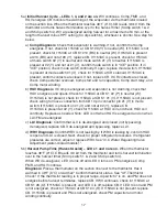
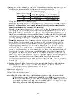
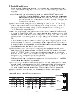
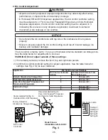
Pump-Out Cycle – LEDs 1, 3, and 5 are on (10/20 second pump-out).
Timing of the
first pump-out is determined by S4 dip switch 5. See the table below.
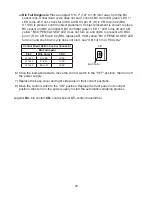
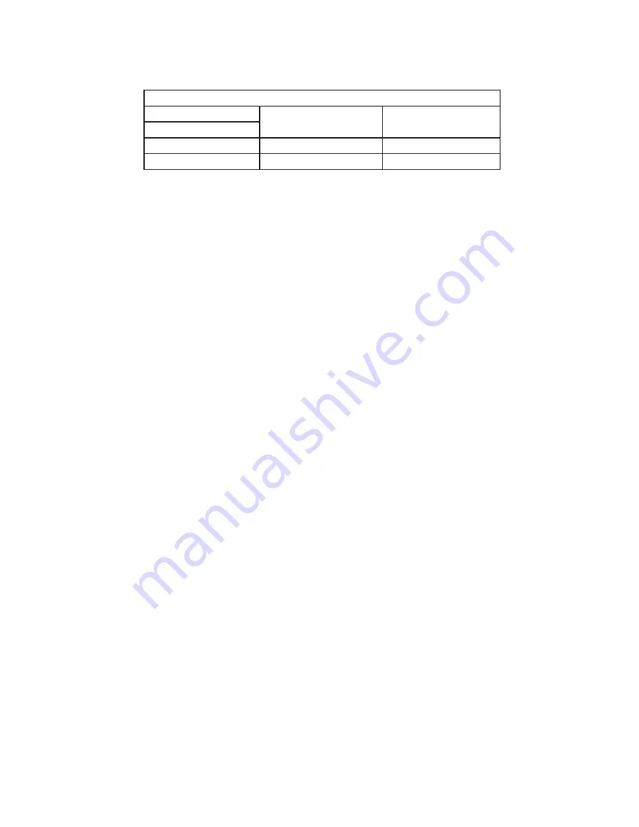
Control Board Settings
S4 Dip Switch Setting
Pump-Out Frequency
Control Board
No. 5
OFF
Every 10 cycles
After 11th freeze cycle
ON
Every cycle
After 2nd freeze cycle
Comp and FMR continue, HGV energizes.
Note: If S4 dip switch 3 & 4 are set to 3 off and 4 on, LED 4 turns on and WV energizes.
NOTICE!
S5 dip switch 1 must not be adjusted. This is the pump-out circulation
selection and allows DV to energize in pump-out.
FM and LLV de-energize. PM stops for 2 sec., then PM and DV energize for 10/20 sec.
depending on pump-out timer (S4 dip switch 3 & 4) setting. When the pump-out timer
terminates, pump-out is complete. The pump-out frequency control (S4 dip switch 5) is
factory set, and generally no adjustment is required. However, the pump-out frequency
control can be set to have a pump-out occur every 10 cycles or every cycle. For details,
see "III.C.4. Pump-Out Frequency Control (S4 dip switch 5)."
Pump-Out Diagnosis
: In the freeze cycle before pump-out (see table above), after
5 min. of freeze disconnect CB black K5 connector (FS connector). Check that PM
stops and re-starts. Next, check that PM and DV energized (water flowing down the
drain through DV). If PM does not stop and re-start, check that CB LEDs 1, 3, and
5 are on. If not, replace CB. If LEDs 1, 3, and 5 are on and PM does not energize,
check for 115VAC at CB K1 #4 (R) to neutral (W). If 115VAC is not present, replace CB.
If not, check PM motor windings and impeller for binding. If energized, make sure DV
energized. If not, check for 115VAC at CB K1 #5 (W/BU). If 115VAC is not present and
LED 5 is on, replace CB. If 115VAC is present, check DV solenoid continuity. Replace as
needed. If DV is energized and open, check that the drain line is not clogged.
Confirm FM and LLV de-energize. If FM or LLV are energized with LEDs 1, 3, and 5 on,
replace CB.
8)
Normal Harvest Cycle
– Same as the initial harvest cycle. Return to step 5a) above.
Note: Appliance continues to cycle until BC is satisfied or power is switched off.
The appliance always restarts at the 1-min. fill cycle.
2. Shutdown Diagnosis
1)
See "II.D.1. Bin Control Check."
Legend:
BC
–bin control;
CB
–control board;
Comp
–compressor;
CR
–compressor relay;
CT
–control transformer;
DV
–drain valve;
FM
–fan motor;
FMR
–fan motor remote;
FS
–float switch;
HGV
–hot gas valve;
HM
–headmaster (C.P.R.);
HPS
–high-pressure
switch;
LLV
–liquid line valve;
PM
–pump motor;
TXV
–thermostatic expansion valve;
WRV
–water regulating Valve;
WV
–inlet water valve
Summary of Contents for KM-350MAJ
Page 58: ...58 7 KM 660MWJ DATA PENDING ...


