41
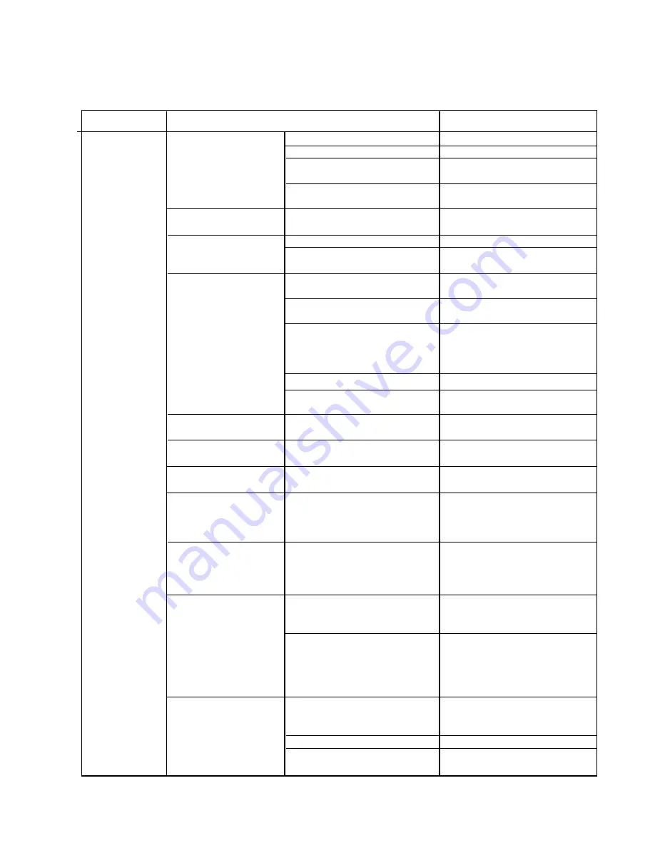
PROBLEM
POSSIBLE CAUSE
REMEDY
[1] The icemaker
a) Power Supply
1. “OFF” position.
1. Move to “ON” position
will not start
2. Loose connections.
2. Tighten
3. Bad contacts.
3. Check for continuity and
replace.
4. Voltage too high.
4. Check and get
recommended voltage.
b) Fuse (Inside Fused
1. Blown out.
1. Check for short circuit
Disconnect, if any)
and replace
c) Control Switch
1. “OFF” position.
1. Move to “ICE” position.
2. Bad contacts.
2. Check for continuity and
replace.
d) Bin Control
1. Tripped with bin filled
1. Remove ice.
Thermostat
with ice.
2. Ambient temperature
2. Increase ambient
too cool.
temperature.
3. Set too warm.
3. See “II.2.[d]
For mechanical
CONTROLS AND
bin control
ADJUSTMENTS, 5) Bin
see “II. 3. [c]”
Control.”
4. Bulb out of position.
4. Place in position.
5. Bad contacts or leaks
5. Check for continuity and
bulb.
replace.
e) High Pressure
1. Bad contacts.
1. Check for continuity and
Control
replace.
f) Transformer
1. Thermal fuse blown out
1. Replace.
or coil winding opened.
g) Wiring to
1. Loose connections or
1. Check for continuity and
Controller Board
open.
replace.
h) Thermistor
1. Leads short-circuit or
1. See “II.2.[d] CONTROLS
open and High
AND ADJUSTMENTS, 1)
Temperature Safety
Defrost Control.”
operates.
i) Hot Gas Solenoid
1. Continues to open in
1. Check for power off in
Valve
freeze cycle and High
freeze cycle and replace.
Temperature Safety
operates.
j) Water Supply Line
1. Water supply off and
1. Check and get
water supply cycle does
recommended pressure.
not finish.
2. Condenser water pressure
2. Check and get
too low or off and Pressure
recommended pressure.
Control opens and closes
frequently to finally operate
High Temperature Safety.
k) Water Solenoid
1. Mesh filter or orifice gets
1. Clean.
clogged and water supply
cycle does not finish.
2. Coil winding opened.
2. Replace.
3. Wiring to Water Valve.
3. Check for loose connection
or open, and replace.
IV. SERVICE DIAGNOSIS
1. NO ICE PRODUCTION
Summary of Contents for KM-500MAH
Page 28: ...28 III TECHNICAL INFORMATION 1 WATER CIRCUIT AND REFRIGERANT CIRCUIT a KM 500MAH ...
Page 29: ...29 b KM 500MWH ...
Page 30: ...30 c KM 500MRH ...
Page 34: ...34 b KM 500MRH with auxiliary codes M 2 and after ...
Page 35: ...35 3 TIMING CHART ...
Page 36: ...36 ...


