Page 7
5. Inside the control panel, locate the terminal block (TB-1).
6. Remove existing power cord.
7. Connect the #10 AWG, BLACK wire from the sub-panel 30 amp GFCI breaker [terminal L1] to TB-1 terminal L1.
8. connect the #10 AWG, WHITe wire from the sub-panel 30 amp GFcI breaker [terminal N, load neutral] to TB-1 terminal N.
9. connect the #10 AWG, GReeN wire from the sub-panel GRouNd bar to TB-1 terminal GRouNd.
The GFcI breaker inside the sub-panel supplies all of the power to the spa. Before each use, open the sub-panel and press the TesT button
located on the sub-panel GFcI breaker. The breaker should snap into the “tripped” position and the spa should stop operating. Reset the sub-panel
GFcI breaker by completely pressing the breaker switch down, into the oFF position. Then, flip the breaker switch up, into the oN position. Power
should be restored and the spa should resume operation.
If the GFcI breaker fails to operate in this manner, it is an indication of an electrical malfunction and the possibility of an electric shock. disconnect
the power until the fault has been identified and corrected.
ImpoRtaNt:
should you ever find the need to move or relocate your
Hot Spot
spa, it is essential that you understand and apply these
installation requirements. your
Hot Spot
spa has been carefully engineered to provide maximum safety against electric shock. Remember,
connecting the spa to an improperly wired circuit will negate many of its safety features.
230 VOlT CONVERSION, 50 AMP
(SX & TX)
Conversion instructions
Note:
An Authorized
Hot Spot
spa Technician must reconfigure spa using the soft jumpers to allow the heater to run concurrent with jet pump.
A licensed electrician must install the sub-panel (available from your
Hot Spot
spa dealer) to supply
power to the spa. The sub-panel must be placed in sight of the spa, at a minimum distance of 5 feet (1.5 m) away.
Main service
electrical
Panel
230VAc, 50 Amp
2-Pole circuit
cIircuit Breaker
(Non GFcI)
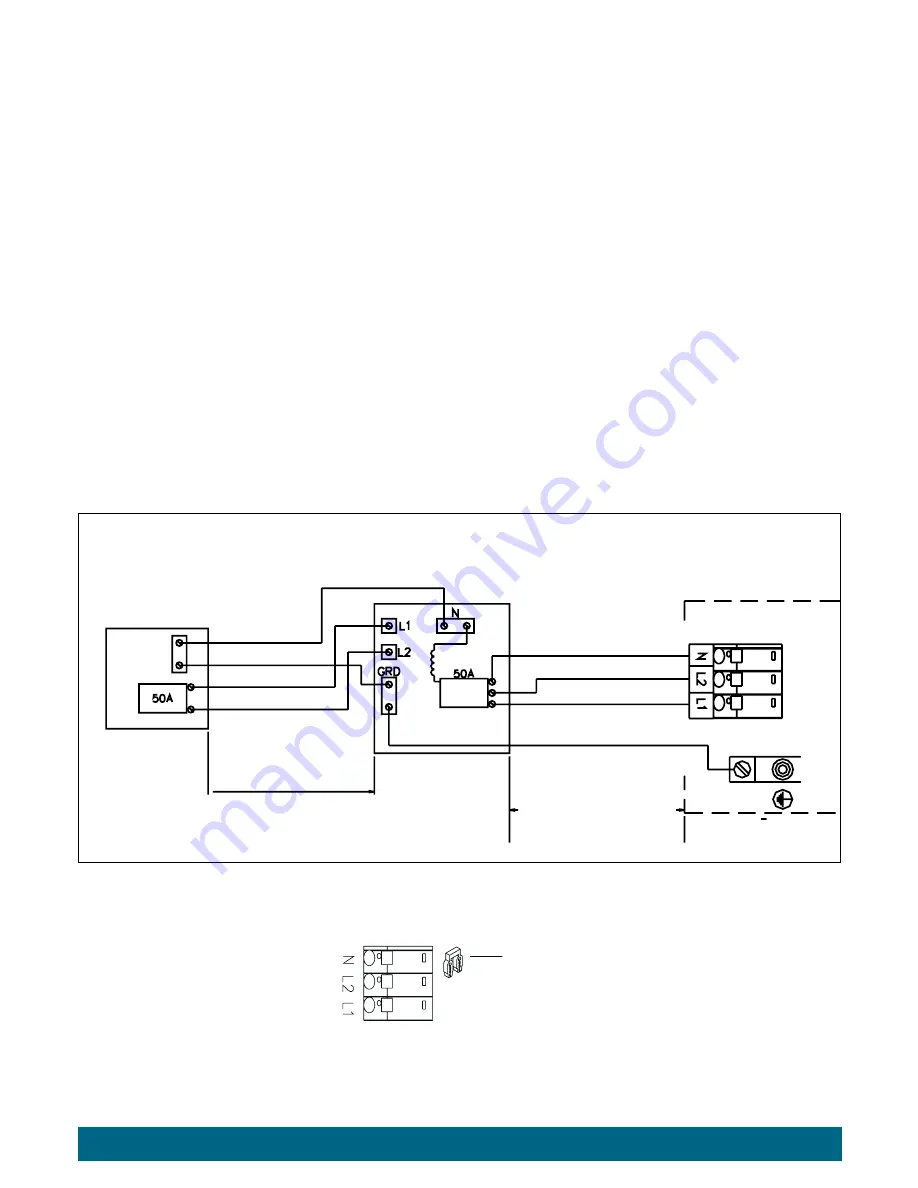
WIRING ILLusTRATIoN
oPTIoNAL 50A/230V suBPANeL coNVeRsIoN coNNecTIoN
230 VAc, 40A, 60HZ, coNVeRTed ModeLs
Less Than 100 FT.
#8 AWG White, Neutral
#10 AWG Green, Ground
#8 AWG Black, L1
#8 AWG Red, L2
sub-Panel
with GFcI
Breakers
More than 5 feet
the sub-Panel must be
within sight of the spa
do Not exceed 50 Feet
control Box
N, Neutral, #8 AWG White
L1, Hot, #8 AWG Black
Ground, #10 AWG Green
L2, Hot, #8 AWG Red
2 Position Power Jumper
must be removed on the
Terminal Block to operate
230 VAc spa Models
Power Jumper Position
see Wiring
Illustration
230 VAc Wiring
(50A converted)
Electrical Installation
page 7
Summary of Contents for 2014 REL
Page 1: ...2014 Owner s Manual...
Page 47: ......


