background image

SAFETY EQUIPMENT 

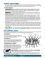
A.  GFcI: The Ground Fault circuit Interrupter, located on the end of the power cord (115 Volt models only), is a safety device that is designed to 

sense as little as 5 milliamps of electrical current leakage to ground. It is very important to protect a GFcI from rain and other moisture. Watkins 

Manufacturing corporation recommends that the GFcI be tested before each use to ensure it is functioning correctly. 

To TEST THE gFCI:


Cord-Connected models: 

Before each use, with the spa operating, push the TesT button (located on the front of the GFcI). The GFcI 

breaker should trip to the “off” position, disconnecting power to the spa. Reset the GFcI by pushing the ReseT button. The spa will now 

operate normally. If the interrupter does not perform in this manner, it is an indication of an electrical malfunction and the possibility of an 

electric shock. unplug the spa until the fault has been identified and corrected.


Hard Wired models:

 The GFcI breaker is located inside the subpanel, before each use of the spa and with the unit operating, push the 

Test button on each breaker. The switch should click over to the “Trip” position. Wait 30 seconds and reset each GFcI breaker by switching 

it completely off and then completely on. The switch should then stay on. 

B. 

HeateR HIGH-lImIt SWItCH: 

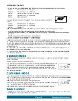
The heater high-limit sensor is located on the heater assembly. If for any reason the internal temperature 

of the heater exceeds 119°F (48°c), the high-limit circuit will trip and turn off the spa. The control panel display will display - - - - - and the 

ReAdy incon will flash for the all spa models. The heater high-limit may be reset when the water temperature within the heater has cooled 

to approximately 110°F (43°c). Reset the heater high-limit by simply disconnecting power to the spa for thirty seconds. The cause of the 

overheating must be located to prevent a recurrence. The most common cause of limit-tripping is inadequate water flow through the heating 

system. This may be caused by an obstruction within the pump water lines (filter, pump intakes or internal plumbing), the non-function of the 

low-speed mode of the jet pump, or the malfunction of the control thermostat. once the cause has been identified and corrected, and the 

sensor has cooled, reset spa by simply disconnecting power to the spa for thirty seconds.

c. 

pReSSURe SWItCH:

 The pressure switch is located inside the control box on the heater, and is designed to prevent heater operation during 

a no or low flow condition. If for any reason flow through the heater is reduced or stopped, the pressure switch will trip. If the pressure switch 

has detected a no or low flow condition ===== will display for all spa models. The most common causes of inadequate heater flow are a dirty 

or clogged filter, obstruction in the plumbing lines, and non-operation of the low speed heat pump. Additionally, the control panel will display 

===== for all spa models if the pressure switch senses flow through the heater when the jet pump is not activated. contact your Authorized service 

Technician if displayed.

d.

   CoNtRol tHeRmoStat: 

The control thermostat helps regulate the temperature of the water. If for any reason something were to happen to 

this device, the 

READY


icon on the control panel will flash for the 

tempo

Relay

RHytHm

, sX & TX spa models.  contact your Authorized 

service Technician.

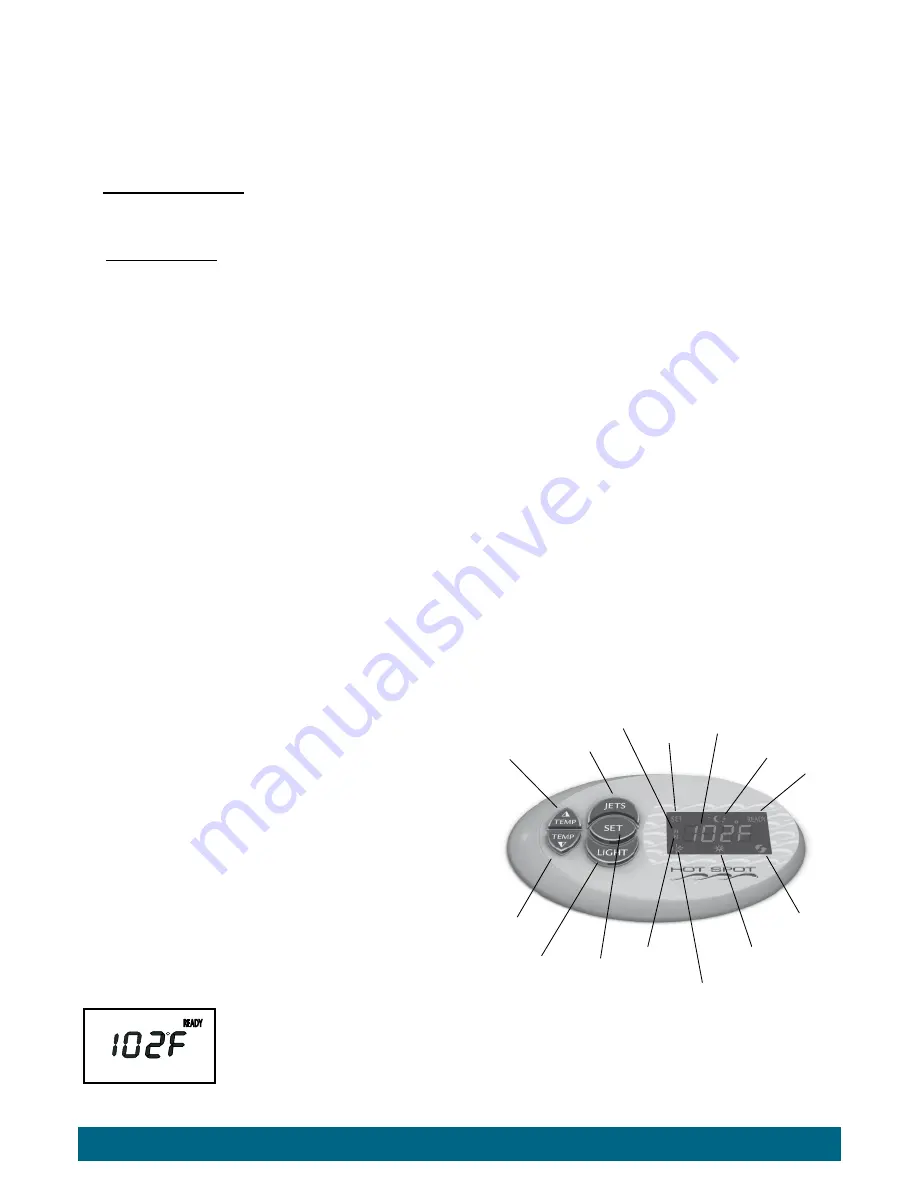
SPA CONTROl PANEl

your control panel consists of an Led display and convenient touch pads that allow you to set the water temperature and adjust the skim/filter cycle 

settings, lock spa temp, lock entire spa functions, as well as control the hydrotherapy jets, and lights from spa-side.

lEd dISplAY

The Led display on your spa-side control panel continually shows the 

spa’s actual water temperature. In certain situations, it will also display 

other messages. see TRouBLesHooTING section.

SET buTTon

use the set button to control clean cycle, filter cycle, locking and light 

functions. To activate the desired mode, press the 

Set

 button. When 

the “seT” icon flashes push the applicable button. The seT mode ends 

after 3 seconds or when the“seT” icon stops flashing.

TEMpErATurE ConTrol

The set temperature range is from 80°F (26°c) to 104°F (40°c). 

Temperatures of any setting may rise slightly depending on the current 

use and condition of your spa, and on outside temperature. Whenever 

power is disconnected and then reconnected to the spa, the water 

temperature setting will automatically return to the last temperature 

entered into the program. 
Pressing the 

temp Up

 (

) button displays the spa’s set temperature. To increase the set temperature, press the 

temp Up

 (

) button again, once for each degree of increased temperature desired. If you hold the 

temp Up

 (

button down, the set temperature will increase by one degree every half second.
Pressing the 

temp Down

 (

) button displays the spa’s set temperature. To decrease the set temperature, press 

the 

temp Down 

(

) button again, once for each degree of decreased temperature desired. If you hold the 

temp Down

 (

) button down, the set 

temperature will decrease by one degree every half second.

Temp / Lock 

 display

Light Icon

Filter cycle Icon

Jets Button

Light Button

Temperature down

Temperature up

set Button

set Icon

sleep 

Icon

Temp

Ready

 Icon

Filter cycle 

2 Icon

Filter cycle 1 

Icon

SET

READY

F1
F2

READY

READY

READY

READY

READY

READY

READY

F1

SET

READY

F1
F2

SET

F1
F2

SET

READY

F1
F2

READY

Jet Icon

TM

operating Instructions 

page 17 

Summary of Contents for 2014 REL

Page 1: ...2014 Owner s Manual...

Page 2: ...Watkins manufacturing Corporation reserves the right to change specifications or design without notification and without incurring any obligation Important In most cities and counties permits will be...

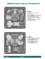
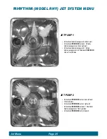
Page 3: ...System Mode 18 Cleaning 18 Tools Menu 19 Audio Menu Optional 21 jet menus Tempo Model TEM 23 Relay Model REL 24 Rhythm Model RHY 25 SX Model SX 26 TX Model TX 27 Water Quality And Maintenance General...

Page 4: ...and equipment protection To ensure proper operation of this important safety device test according to the following instructions per electrical configuration Cord Connected 115 volt 15 or 20 amp model...

Page 5: ...ipping and falling Remember that wet surfaces can be very slippery Take care when entering or exiting the spa People with infectious diseases should not use the spa Keep any loose articles of clothing...

Page 6: ...ssories and recommended spa chemicals and cleaners Don t Leave the Hot Spot spa exposed to the sun without water or the cover in place Exposure to direct sunlight can cause solar distress of the shell...

Page 7: ...l ventilated when it is installed indoors or in a confined area Inadequate ventilation around the spa could cause a build up of a higher than normal concentration of spa chemicals and or bacterial fra...

Page 8: ...the pump is operating in LOW or HIGH speed and the thermostat is calling for heat All electrical connections must be made in accordance with the wiring information contained in the electrical control...

Page 9: ...re from the main electrical service panel to the sub panel GROUND bar 3 Connect the 10AWG BLACK L1 wire from the main electrical service panel to the sub panel terminal L1 4 Check the connections inte...

Page 10: ...t spa it is essential that you understand and apply these installation requirements Your Hot Spot spa has been carefully engineered to provide maximum safety against electric shock Remember connecting...

Page 11: ...anel 50 amp GFCI breaker terminal L2 to TB 1 terminal L2 10 Connect the 8AWG WHITE wire from the sub panel 50 amp GFCI breaker terminal N load neutral to TB 1 terminal N 11 Connect the 10AWG GREEN wir...

Page 12: ...nel 5 Connect the 8AWG WHITE NEUTRAL wire from the subpanel breaker to the Neutral terminal on the spa s control box 6 Connect the 8AWG BLACK L1 wire from the subpanel breaker to terminal L1 on the sp...

Page 13: ...icensed electrician CERTIFICATIONS ETL Listed OVERHEAD VIEW A Air Control Lever B Control Panel C Filter Compartment Cover D Temperature Sensor E Directional Precision Jet F Directional Hydromassage J...

Page 14: ...must be performed by a licensed electrician CERTIFICATIONS ETL Listed OVERHEAD VIEW A Air Control Lever B Control Panel C Filter Compartment Cover D Temperature Sensor E Directional PrecisionJets F Di...

Page 15: ...ing must be performed by a licensed electrician CERTIFICATIONS ETL Listed OVERHEAD VIEW A Air Control Lever B Control Panel C Filter Compartment Cover D Temperature Sensor E Directional PrecisionJets...

Page 16: ...130 lbs per sq ft 635 kg per m ELECTRICAL REQUIREMENTS 115 volt 20 amp grounded circuit 115 volt 30 amp grounded circuit optional requires 30 amp subpanel 230 volt 50 amp single phase G F C I circuit...

Page 17: ...0 lbs per sq ft 488 kg per m ELECTRICAL REQUIREMENTS 115 volt 15 amp grounded circuit 115 volt 30 amp grounded circuit optional requires 30 amp subpanel 230 volt 50 amp single phase G F C I circuit op...

Page 18: ...fully operational as indicated by strong non surging jets priming of the spa is complete If you do not feel a steady stream of water from your jets refer to the instructions for priming the pump in t...

Page 19: ...temperature has occurred In either electrical configuration when the high speed mode of the jet pump is turned off the spa will enter a ten minute tranquil mode During this time the heating system and...

Page 20: ...pressure switch has detected a no or low flow condition will display for all spa models The most common causes of inadequate heater flow are a dirty or clogged filter obstruction in the plumbing line...

Page 21: ...ystem after 6 hours of continuous operation The light symbol on the panel will also turn off when the lights are deactivated If the lights will not turn on make sure spa Lock is deactivated spa Lock d...

Page 22: ...luminated on the display Press the TEMP button to deactivate the SPALOCK feature Lock Override The Lock Override feature is for spa users who normally keep the set temperature locked Should the user w...

Page 23: ...leep Mode feature A Press the SET button until the TOOLS menu is illustrated B Press the TEMP button to enter the TOOLS submenus C Press the SET button until ECON is illuminated on the display D Press...

Page 24: ...o increase volume and the Temp button to decrease volume NOTE Volume range is from 0 40 No number displayed indicates Volume is OFF TO PAUSE PLAY From theAUDIO menu 1 Press the Temp button to display...

Page 25: ...e of four audio sources IPOD TV AUX BLUE 2 Press the SET button to display TRE 3 Press the SET button to display BAS 4 Press the SET button to display BAL 5 to 5 5 Press the Temp button to raise the B...

Page 26: ...e Jet 2 Rotary Hydromassage Jets and 4 Directional Precision Jets in lounge 2 Directional Precision Jets and 1 Directional Hydromassage Jet on Left wall jet Pump 2 10 Directional Precision Jets on lef...

Page 27: ...t wall 2 Directional Precision Jets and 1 Directional Hydromassage Jet on Left wall 2 Directional Precision Jets in footwell Jet Pump 2 4 Directional Precision Jets and 2 Rotary Hydromassage Jets on b...

Page 28: ...all 2 Directional Hydromassage Jets 1 Rotary Hydromassage Jet and 2 Directional Precision Jets on front left side Jet Pump 2 8 Directional Precision Jets on back left wall 1 Water feature 3 Directiona...

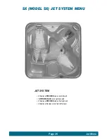
Page 29: ...SX Model SX Jet System Menu Jet System 8 Directional Precision Jets on back left wall 1 Moto Massage Jet on right back wall 2 Directional Precision Jets on front right wall 2 Directional Precision Jet...

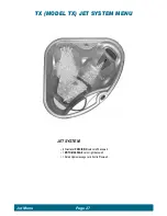
Page 30: ...Page 27 TX MODEL TX Jet System Menu Jet System 8 Directional Precision Jets on left back wall 1 Moto Massage Jet on right back wall 1 Rotary Hydromassage Jet in front left footwell Jet Menu Page 27...

Page 31: ...come in either liquid or tablet form FreshWater Test Strips are a convenient testing method used by many spa owners Keep in mind that test strips are susceptible to heat and moisture contamination wh...

Page 32: ...en the spa is filled proceed to the Start Up and Refill Procedures on page 15 Balancing the Total Alkalinity TA A The recommended TotalAlkalinity TA for your spa water is 40 120 ppm B TotalAlkalinity...

Page 33: ...chemicals and the type of sanitizer used F When the pH is within the recommended range proceed to the final step Maintaining the sanitizer level A Sanitizer is extremely important for killing algae ba...

Page 34: ...treatment than MPS one teaspoon of sodium dichlor has oxidizing capabilities comparable to two tablespoons of MPS Sodium dichlor may be a more appropriate weekly shock for those users that experience...

Page 35: ...it is subjected to the continuous flow of water created by the pump s 24 hour circulation The flowing water through a chemical erosion process carries with it the silver ions necessary to add a sanit...

Page 36: ...he chlorine smell and to allow the proper level of free chlorine to be maintained When giving your water a super chlorination treatment open the cover at least half way for twenty minutes to allow the...

Page 37: ...purified water Cleaning the Ozone Injector On occasion a mineral build up may clog the ozone injector causing a lack of flow or low flow of ozone bubbles To prevent this refer to the following instruc...

Page 38: ...period of time the sanitizer level dispensed by the floater will fall to near zero Alow sanitizer level will allow viruses bacteria or algae to grow 2 Floaters tend to stay in one area of the spa mos...

Page 39: ...easure of the spa water s acidity and alkalinity The recommended pH for the spa water is 7 2 to 7 6 Below 7 0 considered neutral the spa water is too acidic and can damage the heating system Above 7 8...

Page 40: ...the pillow IMPORTANT Just pulling the pillow straight up and out of the shell recess will eventually damage the pillow This abuse is not covered under warranty 3 To reinstall the spa pillow carefully...

Page 41: ...simulated wood consists of simply spraying the cabinet with a mild soap and water solution to remove any stains and residue DRAINING YOUR SPA 1 TURN OFF OR DISCONNECT POWER FROM THE SPA 2 Locate the...

Page 42: ...on is coming from another jet block off the other jet using a large rag this will help pull out the water that is trapped deeper inside the main line b Filter suction fittings and filter compartment c...

Page 43: ...blockage within the system plumbing 2 switch malfunction in the heater circuit or 3 the low speed mode of the jet pump is not functioning 5 If the heater high limit has tripped the control panel displ...

Page 44: ...surface material can withstand this kind of abuse damage to components or spa surface caused by improper water chemistry maintenance and damage to the spa surface caused by leaving the spa uncovered...

Page 45: ...tripping still occurs call for service Set water temperature significantly different from display temperature System Controls Disconnect power to the spa for at least thirty seconds Contact an Authori...

Page 46: ...to allow the air to escape When water is present hand tighten the union Turn power back on activate the pump and check to make sure union is tight enough to keep it from leaking Re install equipment d...

Page 47: ......
Page 48: ...SXC TX Model TX TXC 2013 Watkins Manufacturing Corporation Hot Spot Tempo Relay Rhythm Precision No Fault FreshWater FreshWaterAg EverFresh Clean Screen and Vanishing Act are trademarks of Watkins Ma...

Reviews: