4
HEATPAD SAUNA ENVIRONMENT
CONTROLLER
GENERAL
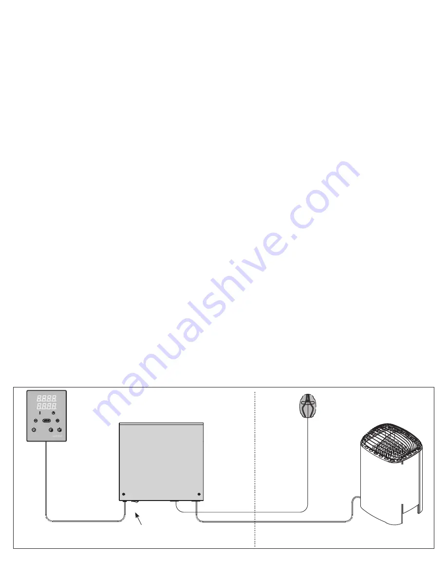
The control unit consists of a control
panel, a power unit and a sensor. See
figure 1.
The control unit regulates the temperature
in the sauna room based on information
given by the sensor. The temperature
sensor and the overheat protector are
located in the sensor box. The temperature
is sensed by an NTC thermistor, and there
is a resettable overheat protector (see
section 3.4.).
The control unit can be used to delay the
start of the heater (timer delay). See figure
3.
TECHNICAL DATA
Control Panel:
• Temperature adjustment range 104 -
194°F (40 - 90°C)
• Pre-setting time adjustment range 0 -
12 h
• Lighting control, max. power 100W,
120V, 1Ph
• Fan control, max. power 100W, 120V,
1Ph
• Dimensions: 3.4” x 1” x 4.4”
• 50’ control cable length
Power Unit:
• Supply voltage
HeatPad 10: 240V 1Ph, 208V 3Ph
HeatPad 15: 240V 1Ph, 208V 3Ph
• Max. load
HeatPad 10: 6kW 240V 1Ph
10kW 240V 1Ph (with dual
Figure 1. Control Unit Components
Control Panel
Temperature Sensor
Heater
(not included)
Power Unit
Dry Area
S
auna R
oom
Main Switch
circuits)
10kW 208V 3Ph
• HeatPad 15: 8kW 240V 1Ph
15kW 240V 1Ph (with dual circuits)
15kW 208V 3Ph
• Dimensions: 14.3” x 2.9” x 10.5”
Sensor:
• Temperature Sensor NTC thermistor
22kΩ/T=77°F (25°C)
• Resettable overheat protector
• Dimensions: 2.0” x 2.9” x 1.1”
• 50’ sensor cable length


