A1 A2 L1 L2 L3 GRD
A1 A2 L1 L2 L1 L2 GRD
A1 A2 L1 L2 GRD
GND N L1 L2
GND N L1 L2 L1 L2
GND N L1 L2
K2
K1
L
N
GND
A4 A3 A2 A1 U2 U1
N N L2 L1
L N
GND
Yell
ow
Red Whi
te
Blue
1 2 3 4
1 2 3 4
A1
A2
A1
A2
1 2 3 4
1 2 3 4
S
208V 3
P
h
240V 1
P
h
L2
L2
L2
L2 L2
L1 L1
L1
L1 L1
L1 L3
L3
L2
A2 A2
A1 A1
N N
A
1
A
2
A
3
A
4
X2
F3
F1
F2
15
CLUBHEA
T SERIES SA
UNA HEA
TER
S ONL
Y
K1 & K2 = contactor
s (30A in HeatP
ad 1
0 or 45A in HeatP
ad 1
5)
S = Main S
witc
h
F1 = Break
er for relay outputs (T2.5AH, Ceramic Slow
Type)
F2 = Break
er for electronic card (T40mA, Slow
Type)
F3 = Break
er for relay outputs (T2.5AH, Ceramic Slow
Type)
HeatP
ad1
0 / CX30-U1
-U3
HeatP
ad1
5 / CX45-U1
-U3
Multidri
ve
Temperature
S
ensor
Control
Panel
remote
X
14
X
16
X
13
Data
Cable
Contacts for safety devices
X1
3: safety switc
h
X1
6: N (shared)
X1
4: remote switc
h on/of
f
U = 1
0V
Fa
n
120V 1Ph
Max 1
00W
Lighting
120V 1Ph
Max 1
00W
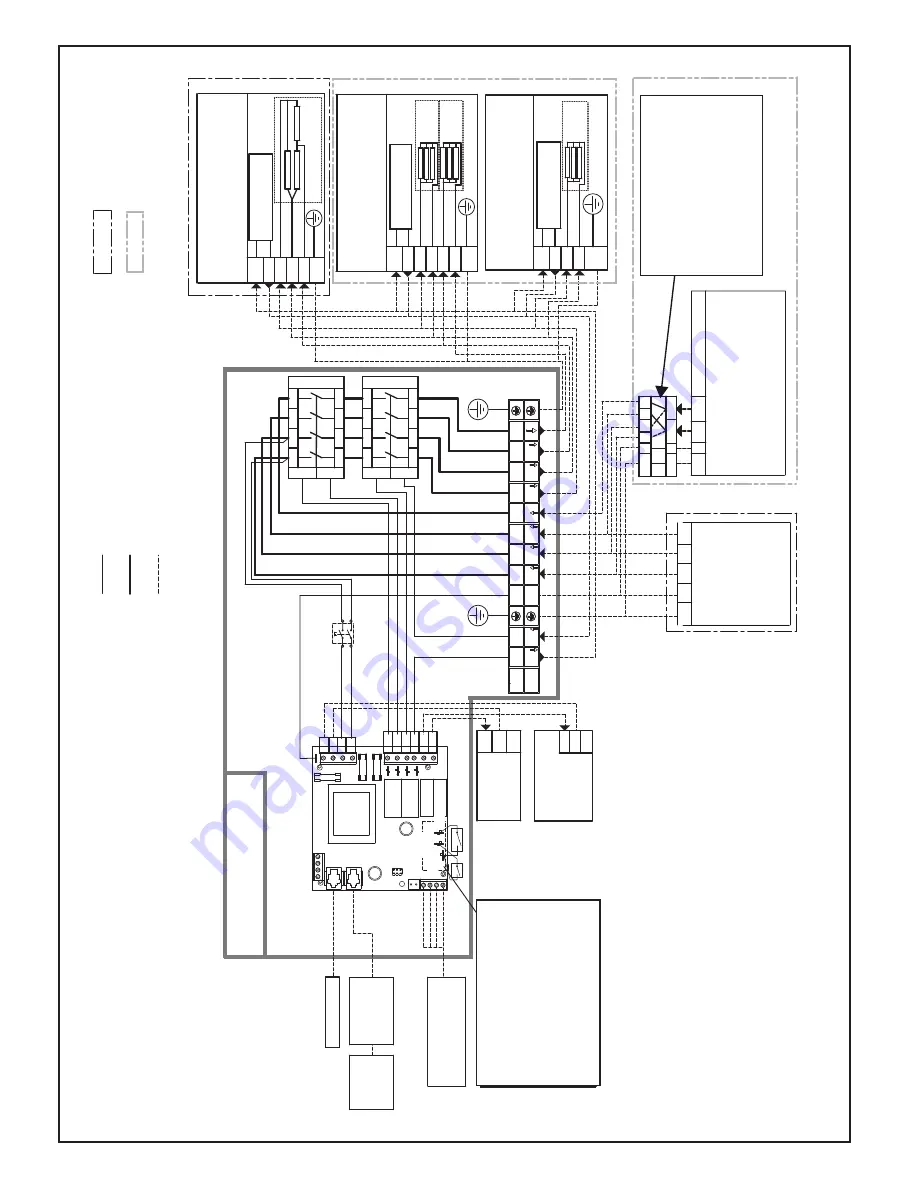
Figur
e 6.2 Electr
ical connections (HeatP
ad1
0/CX30-U1
-U3 and HeatP
ad15/CX45-U1
-U3) f
or ClubHeat Sauna Heat
er models
(C1
00
0/K1
0G-U1,
C1250/12.5G-U1,
C150
0/K15G-U1,
C1
00
0-3/K1
0G-U3,
C1250-3/K12.5G-U3,
and C150
0-3/K15G-U3).
Heater
s 240V 1Ph (single circuit)
HeatP
ad 1
0: 6 kW max
HeatP
ad 1
5: 8 kW max
Dual circuit installations
2 pole 2 break
er subpanel
load center shall be
supplied by electrical
contractor
Heater
s 240V 1Ph (dual circuit)
HeatP
ad 1
0: 1
0 kW max
HeatP
ad 1
5: 1
5 kW max
Heater
s 208V 3Ph
HeatP
ad 1
0: 1
0 kW max
HeatP
ad 1
5: 1
5 kW max
NO
TE:
F
or subpanel detail
please refer to local code.
Factory wiring (1
8
A
WG)
208V 3Ph
240V 1Ph
Factory wiring 2x (1
0
A
WG)
Installation wiring
Overheat
Protector
Overheat
Protector
Overheat
Protector
Single
Circuit
Single
Circuit
Circuit
1
Circuit
2
safety
Main electrical panel
240V 1Ph
Max 30
A per cable (HeatP
ad1
0/
CX30-U1
-U3)
Max 45
A per cable (HeatP
ad1
5/
CX45-U3-U1)
Main electrical panel
208V 3Ph
Max 30
A (HeatP
ad 1
0/
CX30-U1
-U3)
Max 45
A (HeatP
ad 1
5/
CX45-U1
-U3)


