18
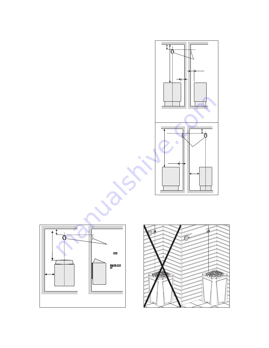
Figure 8. The placement of the
temperature sensor of the control
unit in connection with floor-mounted
heaters.
A / D = Safety distance of heater
(Check from heater manual)
INSTALLING THE TEMPERATURE
SENSOR
Floor-mounted heaters (see figure 8)
• The temperature sensor is mounted
on the wall above the heater, along
the vertical center line running parallel
to the sides of the heater, at a distance
of 3-15/16” from ceiling.
Wall-mounted heaters (see figure 9)
• The temperature sensor is wall-
mounted above the heater, along the
vertical center line running parallel to
the sides of the heater, at a distance of
3-15/16” from the ceiling.
A / D = Safety distance of heater
(Check from heater manual)
Figure 10. Sensor’s minimumdistance
from an air vent
Figure 9. The placement of the
temperature sensor of the control
unit in connection with wall-mounted
heaters
3-15/16”
min 40”
Sensor
D
A
3-1
5/1
6”
3-15/16”
D min.
D min.
A min.
A min.
A min.
A min.
Sensor
Sensor
NOTE! The wire of the sensor can be
extended with similar type of wire. Not
exceeding 80’ (25m).
RESETTING THE OVERHEAT
PROTECTOR
The sensor box contains a temperature
sensor and an overheat protect. An NTC
thermistor senses the temperature, and
the resettable overheat protector cuts off
the heater power in a case of malfunction,
after which the protect can be reset. See
figure 11.
Note! The reason for the going off must be
determined before the button is pressed.


