-7-
LOCATING THE FURNACE
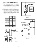
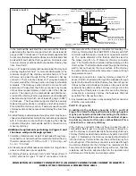
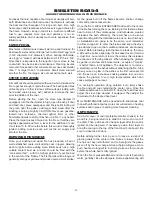
1. The furnace should be located in the same room as the
central system and as close as possible, but not closer than
9". There should be no wall between the furnace and the
warm air outlet duct that is connected directly to the warm
air outlet plenum of the central furnace. (See Fig. 4)
2. Place the furnace on a noncombustible floor.
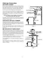
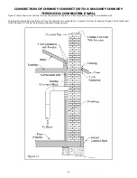
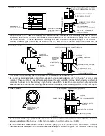
3. Check figures 3 through 5. Be sure you have the clearances
shown below from the furnace and the connector pipe to
combustible surfaces. If you have a solid brick or stone wall
behind your furnace, you can place the furnace as close as
you wish to the wall. If the wall is only faced with brick or
stone, treat it as a combustible wall.
18"
18"
6" SOLID DAMPER
6" BAROMETRIC
DRAFT REGULATOR
NON-COMBUSTIBLE FLOOR
12"
9"
48"
18"
CENTRAL
FURNACE
6" CHIMNEY
21"
Figure 4
Figure 5
1300
1500
Unit to Sidewall
12"
(305mm)
12"
(305mm)
Unit to Backwall
30"
(760mm)
30"
(760mm)
Front of Unit to
Combustible
48"
(1.22m)
48"
(1.22m)
Chimney Pipe
to Sidewall
18"
(460mm)
21"
(530mm)
Chimney Pipe
to Backwall
18"
(460mm)
18"
(460mm)
Plenum to
Combustibles
6"
(150mm)
6"
(150mm)
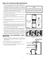
2" MIN. AIR SPACE
REQUIRED BY CODE
CENTRAL
FURNACE
6" MIN.
PLENUM
TO
CEILING
Figure 3
Summary of Contents for 1300
Page 6: ... 6 DIMENSIONS OF FURNACE Figure 2 Model 1500 Figure 1 Model 1300 ...
Page 24: ... 24 CENTRAL INSTALLATION ADD ON INSTALLATION ...
Page 26: ... 26 INSTALLATION D INSTALLATION E ...
Page 27: ... 27 INSTALLATION F INSTALLATION G ...
Page 28: ... 28 INSTALLATION H TOP VIEW FRONT VIEW ...
Page 31: ... 31 NOTES ...
Page 55: ... 6 DIMENSIONS DE LA FOURNAISE Figure 2 Models 1500 Figure 1 Model 1300 ...


