background image

User Manual: HotDog

TM

 Patient Warming System Controller

Page 19

   Power Cord

4.6 m (15 ft) - May vary by country and region per local requirements and 

regulations.

   Device Ratings

Input: 100-240 VAC, 50/60 Hz, 850VA 
Output A & B: 48 VDC, 480 VA Max each
Output C: 240 VA Max
Output D & E: 48 VDC, 144 VA Max each

   Fuses

T10AL250V (2 x 5x20mm)

Environmental Conditions

Environmental Conditions for Transport 

and Storage

Temperature: -20°C to 60°C
Humidity: 20% to 80%
Keep Dry

Environmental Conditions for Use

Temperature: 15°C to 25°C
Humidity: 20% to 80%

Classification and Standards

Certifications

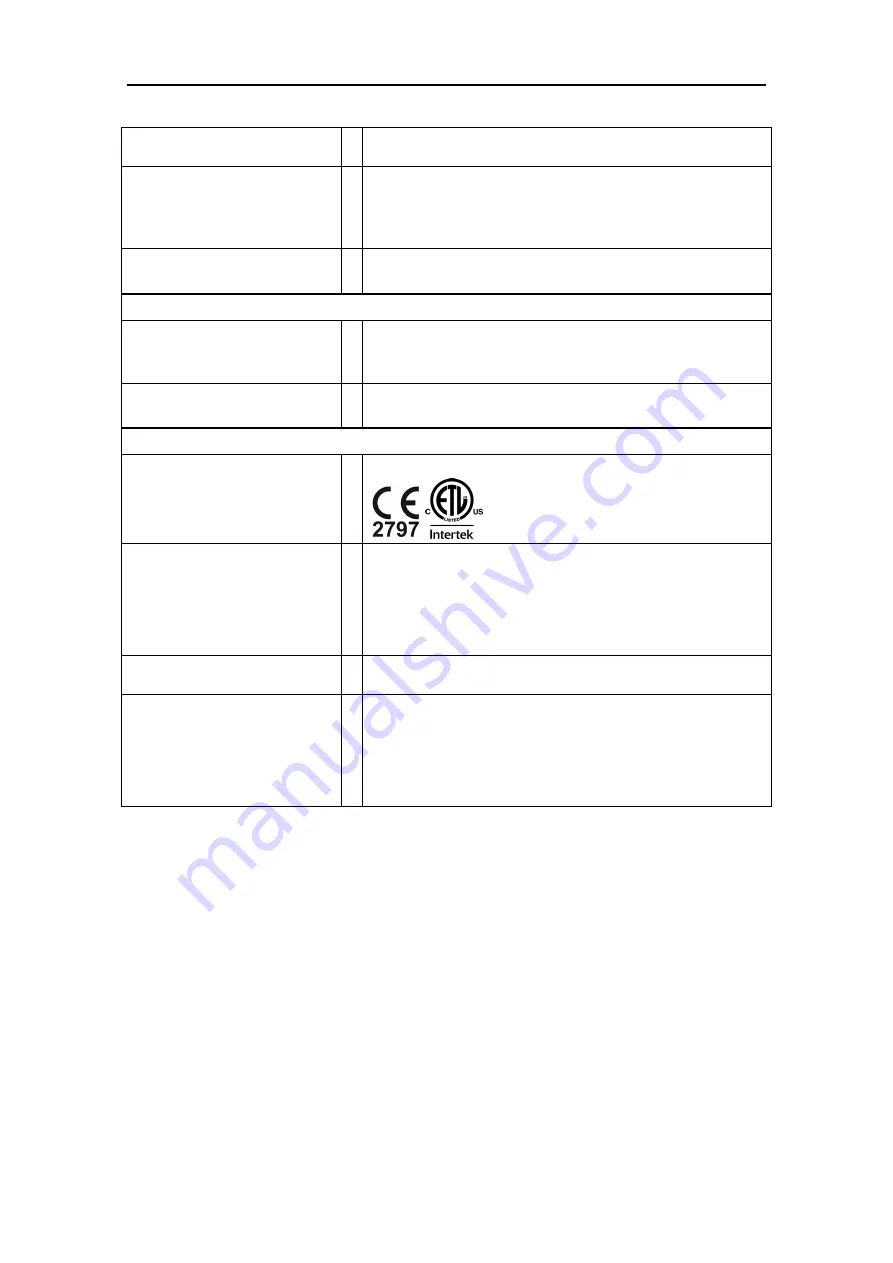
IEC 60601-1; EN 60601-1-2; UL 60601-1; CAN/CSA-C22.2, No. 601.1, EN 55011


Classification

Classified under IEC 60601-1 Guidelines (and other national versions of the 

Guidelines) as Class I, Type BF, Ordinary equipment, Continuous operation. Not 

suitable for use in presence of flammable anesthetic mixtures with air or with 

oxygen or nitrous oxide. Classified by Intertek Testing Services NA Inc. with 

respect to electric shock, fire, and mechanical hazards only, in accordance with 

UL 60601-1. Classified under the Medical Device Directive (93/42/EEC) as a Class 

IIb device.  Classified under the Canadian Medical Device Regulation as Class II.

Diagnostics

A qualified technician can perform general system testing. The Controller has no 

user serviceable parts.

Important Information

This device complies with the EMC requirements according to IEC 60601-1-2. 

Radio transmitting equipment, cellular phones, etc. shall not be used in the 

close proximity of the device since this could influence the performances of the 

device. Particular precaution must be considered during use of strong emission 

sources such as High Frequency surgical equipment and similar so that, e.g., the 

HF-cables are not routed on or near the device. If in doubt, contact a qualified 

technician or your local representative.

Summary of Contents for WC5 Series

Page 1: ...WC5X User Manual Manufactured by EU Authorized Representative Augustine Temperature Management 6581 City West Parkway Eden Prairie MN 55344 USA TEL 952 465 3500 FAX 952 465 3501 www hotdogwarming com TEL 31 0 70 345 8570 FAX 31 0 70 346 7299 ...

Page 2: ...y 6 Contents 6 Mounting the HotDog Controller to an IV Pole 7 Control Panel Features Operating Modes 8 Alarms 10 Error Codes 10 Instructions for Use 11 Maintenance Cleaning 12 Testing of Indicator Light Function 12 Cleaning General 12 Cleaning Controller 13 Cleaning Warming Devices 13 Technical Support Customer Service 16 Definition of Product Symbols 17 Accessory Part Numbers 17 Specifications 18...

Page 3: ...d on an IV pole or suspended from the OR table gurney rail using optional hooks The HotDog Patient Warming System can be operated continuously to maintain uniform heat under or over the patient depending on which warming device accessory is selected It is the responsibility of the user to determine whether warming is appropriate for each individual patient The HotDog Patient Warming System should ...

Page 4: ...cessories designed for use under the patient Warming Mattress The Warming Mattress is not sterile Take appropriate precautions as necessary to protect the sterile field Accessories and Other Equipment Accessories and cables other than those specified in HotDog User Manuals may result in increased emissions or decreased immunity of the HotDog Patient Warming system The HotDog Patient Warming System...

Page 5: ...hey may cause damage to the product and result in loss of the heating function and or localized heat build up in the damaged area DO NOT place the Warming Mattress over a table joint that will move during surgery DO NOT use the Warming Mattress as a stand alone patient pressure relief system DO NOT place any hard objects e g mattress cables EKG cables hard cautery return pads patient fluid lines e...

Page 6: ...nauthorized person The Patient Warming System components are used in a manner other than described in the User Manuals The Controller is installed in an environment that does not meet the appropriate electrical and grounding requirements The Controller is grounded and should not be attached to an un grounded table intended for use with a hyfrecator or equivalent devices INITIAL SETUP ASSEMBLY Cont...

Page 7: ...eleases Caution To prevent the IV pole from tipping the Controller must be attached at a height that provides stability It is recommended to use an IV pole with a minimum wheelbase radius of 35 6 cm 14 in and to mount the Controller no higher than 112 cm 44 in from the floor Failure to properly mount the Controller may result in IV pole tipping catheter site trauma and patient injury Figure 1 HotD...

Page 8: ...erating Modes Figure 3 HotDog Model WC5X Controls Figure 4 HotDog Ports Mains Power Switch ON Power Indicator When the HotDog Controller is plugged into an electrical outlet and the Mains Power Switch on the back of the Controller is turned ON all displays will illuminate briefly and the ...

Page 9: ...ust Button for the desired port until the desired temperature is displayed The temperature can be selected in one degree increments from 37 43 C for Ports A and B Warming Blankets and 35 39 C for Port C Warming Mattresses The designated warming temperature will flash until the selected temperature is achieved at which time the selected temperature will steadily display Port A B and C Ports A and B...

Page 10: ...o Troubleshooting and Error Codes sections for more details Error Code Alarm Condition E1 on affected port Over temperature alarm Temperature of sensor has exceeded 1 degree above set point E2 on affected port Time to temperature alarm device has not reached selected set point within ten minutes E3 on affected port Over current condition E3 on all ports System over current condition E4 on affected...

Page 11: ...rming device e g Warming Blanket Warming Mattress following instructions in the User Manual provided with the device 5 Insert the warming device connecting cable into the proper port on the Controller Controller Port Warming Device A and B Warming Blanket C Warming Mattress D and E Future approved HotDog accessories Note When the connecting cable is inserted into the Controller an audible beep ind...

Page 12: ...d Moisture will damage the components and thermal injury may result Precautions DO NOT use pure harsh solvents e g MEK acetone etc to clean HotDog components Solvents may damage plastic parts labeling and product finish DO NOT use high level disinfectants e g gluteraldehyde peracetic acid or hydrogen peroxide based solutions The U S Centers for Disease Control CDC recommends against the use of hig...

Page 13: ...cloth avoid pushing fluids into any openings 3 Dry with a separate soft cloth Cleaning Warming Devices Frequency Clean between patient use and when the warming device appears soiled Method Clean the warming devices following protocols for non critical medical devices that may contact intact skin Examples of similar devices are blood pressure cuffs exam table covers operating room table pads and su...

Page 14: ... when the device is unplugged or power is turned off at mains switch Primary or Secondary sensor failure E4 for each port Sensor are reading outside of the useful range Fold detection alarm E5 for each port In warming devices equipped with an over temperature array local overheating caused by folding of the warming blanket will initiate visual and audible alarms The alarm will reset when the devic...

Page 15: ...support Hardware I2C failure EH EH EH System failure If this occurs call customer service for technical support Hardware power supply failure EP EP EP System failure If this occurs call customer service for technical support General System Failure EE EE EE software version 1 06 or lower only System failure If this occurs call customer service for technical support ...

Page 16: ...er when you call for technical support The serial number is located on the back of the Controller If it is necessary to return the Controller for service or repair contact your local supplier or sales representative Augustine Temperature Management 6581 City West Parkway Eden Prairie MN 55344 USA TEL 952 465 3500 FAX 952 465 3501 www hotdogwarming com ...

Page 17: ...fter YYYY MM DD Manufacturer See IFU for Warnings Medical Device See electronic IFU on website at URL provided EU Authorized Representative IPX2 Protected against dripping water when tilted up to 15 Vertically dripping water shall have no harmful effect when the enclosure is tilted at an angle up to 15 from its normal position Conforms to European Medical Device Directive 93 42 EEC Medical Equipme...

Page 18: ...ature sensor is at set point 1 C Primary Over temp Alarm Port C Warming Mattress Alarm sounds when temperature sensor at set point 1 C Secondary Over temp Alarm Ports A and B Warming Blanket Independent electronic circuit shuts the heater off if the Warming Blanket temperature sensor reaches set point 3 C 46 C Port C Warming Mattress Independent electronic circuit shuts the heater off if the Warmi...

Page 19: ...e in presence of flammable anesthetic mixtures with air or with oxygen or nitrous oxide Classified by Intertek Testing Services NA Inc with respect to electric shock fire and mechanical hazards only in accordance with UL 60601 1 Classified under the Medical Device Directive 93 42 EEC as a Class IIb device Classified under the Canadian Medical Device Regulation as Class II Diagnostics A qualified t...

Page 20: ...turer s Declaration Electromagnetic Emissions The HotDog Patient Warming System is intended for use in the electromagnetic environment specified below The customer or user of the HotDog Patient Warming System should assure that it is used in such an environment Emissions test Compliance Electromagnetic Environment Guidance RF emissions CISPR 11 Group 1 The HotDog Patient Warming System uses RF ene...

Page 21: ...1000 4 5 1 kV line s to line s 2 kV line s to earth 1 kV line s to line s 2 kV line s to earth Mains power quality should be that of a typical commercial or hospital environment Voltage dips short interruptions and voltage variations on power supply input lines IEC 61000 4 11 5 UT 95 dip in UT for 0 5 cycle 40 UT 60 dip in UT for 5 cycles 70 UT 30 dip in UT for 25 cycles 5 UT 95 dip in UT for 5 se...

Page 22: ...m Field strengths from fixed RF transmitters as determined by an electromagnetic site survey a should be less than the compliance level in each frequency range b Interference may occur in the vicinity of equipment marked with the following symbol NOTE 1 At 80 MHz and 800 MHz the higher frequency range applies NOTE 2 These guidelines may not apply in all situations Electromagnetic propagation is af...

Page 23: ... of transmitter W 150 kHz to 80 MHz P 2 1 d 80 MHz to 800 MHz P 35 0 d 800 MHz to 2 5 GHz P 7 0 d 0 01 0 12 0 04 0 07 0 1 0 37 0 11 0 22 1 1 2 0 35 0 70 10 3 7 1 1 2 2 100 12 3 5 7 0 For transmitters rated at a maximum output power not listed above the recommended separation distance d in metres m can be estimated using the equation applicable to the frequency of the transmitter where P is the max...

Reviews: