background image


Programmable Multi-Stage Smart Thermostat


Reference  No.:


HTW-MT08  Series 


- 3 -

                                                                            Version 2020-1.0                                                                                             

Tip:  Taking  a  picture  with  a  camera  or  smartphone  can  help  you  not  only  remember  how  wires  are  connected  to  the 

terminals, but can also ensure that you label your wires correctly.


********************************Remove Old Thermostat******************************** 

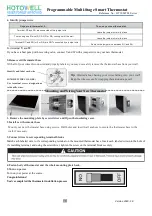
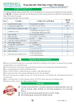
1.Turn Off the Power 


or


To ensure the power to your heating and cooling system has been turned off, try to turn on heating or cooling by changing the 

temperature on your old thermostat


2. Remove the old thermostat cover 

Remove  the  old  thermostat’s  front  cover  from  the  wall  base.  Some  covers  pull  off  easily,  while  others  may  need  to  be 

removed by prying the cover off with a screwdriver.


3. Label wires 

Using your screwdriver, carefully unscrew one wire at a time from the terminal block and attach the corresponding wire label 

sticker. 

Please  note  that  not  all  terminals  may  be  used,  and  that  there’s  no  standard  color  code  for  thermostat  wires,  so  your  wire 

colors may vary.   

For  your  reference,  we’ve  included  a  terminal  label  reference  chart  as  below  to  help  you  connect  the  wires  in  your  old 

thermostat to your new thermostat in case you get stuck. 

Terminal labeling reference chart 


If your current terminal has the following letter


Label the wires with the following letters


Terminal function


RC


RC


24V Power (Cooling)


RH, R, R5, 5


RH


24V Power (Heating)


C


C


24V (Common) from Equipment Transformer


W, W1, 4


W


Heating Relay


Y, Y1


Y


Cooling Relay


G


G


Fan Relay


O


O


Reversing Valve 

(for heat pump applications energized in Cool mode)


B


B


Reversing Valve 

(for heat pump applications energized in Heat mode)


Installation   


Summary of Contents for HTW-MT08 Series

Page 1: ...m USA Italy Wire Diameter for Terminals 2 1 5mm or 1 2 5mm Identify System Type Features Specification SAVE ABOUT 25 ON HVAC ENERGY Save money without compromising your comfort with features like flex...

Page 2: ...Programmable Multi Stage Smart Thermostat Reference No HTW MT08 Series 2 Version 2020 1 0 Display Dimensions...

Page 3: ...g your screwdriver carefully unscrew one wire at a time from the terminal block and attach the corresponding wire label sticker Please note that not all terminals may be used and that there s no stand...

Page 4: ...our wires disconnected and properly labeled you may now safely remove the thermostat base from your wall Mounting and Wiring Your New Thermostat 1 Remove the mounting plate by screw driver and Open th...

Page 5: ...ess to set to set your minute Then press switch to the hour and week day setting respectively press to set the values Programmable Schedule Setting After the above time setting touch the icon each wee...

Page 6: ...ional System 0 Heat Pump System 1 Conventional System 0 Always turn off power at the main power source by removing the fuse or switching the circuit breaker to the off position before installing remov...

Page 7: ...t your region and type in your phone No or email fig 2 3 then you may get a verification code Type in your password and con rm fig 2 4 to complete your registration If you already have an account plea...

Page 8: ...thermostat can not be connected as above steps please try this AP mode connection process On the thermostat During power off status press and hold the arrow icon for 8 sec until the connecting icon a...

Page 9: ...vice name location create group and etc When thermostat runs in programmable mode click the setting symbol at the bottom of the page to switch to the schedule page where you can simply configure the w...

Page 10: ...time Method 1 Click Share with Familay as fig 4 4 Method 2 Click Profile Sent Add Switch on the device Share with New Member Type in the telephone number you would like to share with Method 3 Home pag...

Page 11: ...isplay Check if the terminals between LCD panel and Relay Power Module is loosen 2 Without output but display works Use a new LCD panel or new Relay Power Module for Replacement 3 Room Temp on display...

Reviews: