background image


Programmable Multi-Stage Smart Thermostat


Reference  No.:


HTW-MT08  Series 


- 6 -

                                                                            Version 2020-1.0                                                                                             


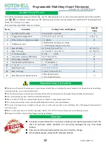
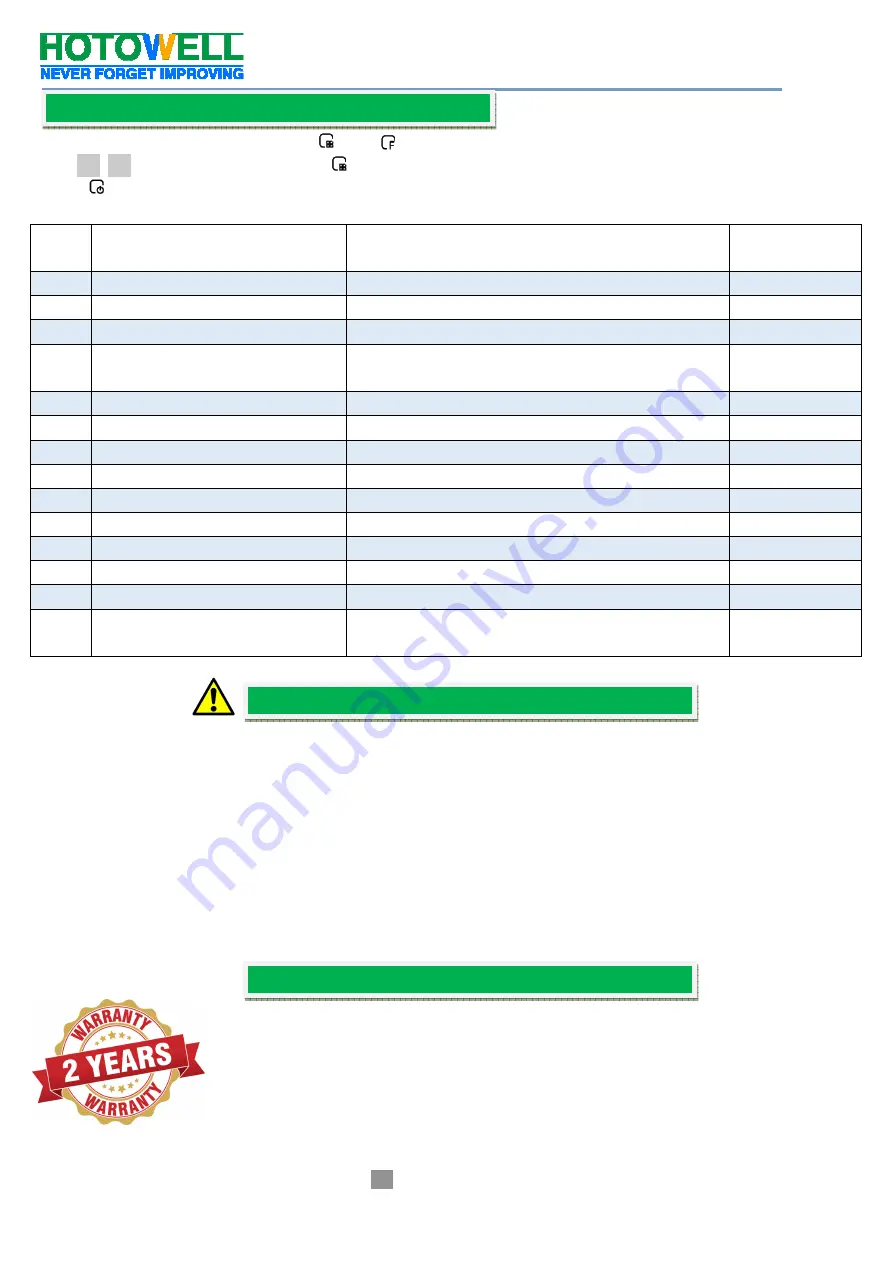
Turn off the thermostat and press and hold 

    and 

  simutaniously for 3 second to enter into Installer Set-Up Process(ISU), 

press 


to configure values and press 

  button again to switch to next parameter. Save and Exit ISU by pressing Power 

button 

  or wait for 3 seconds. 

Parameter items and default value set as below: 

Item 

Function 

Setting Value and Options 

Default 

Value 

Fan ON / AUTO switch 

0=Fan AUTO, 1=Fan ON 

Compensation temperature 

-8 °F to 8 °F (-4 °C to 4 °C) 

-6 °F(-3 °C


Delay setting for compressor output 

1--5 minute 

01 

O/B Reverse Valve 

0=O/B terminal energizes in cooling   

1= O/B terminal energizes in heating 

Min. Set Temp. 

42 °F to 62 °F (5 to 15 °C) 

42 °F (5 °C) 

Max. Set Temp. 

62 °F to 122 °F (15 to 45 °C) 

122 °F(45°C) 

12/24 hours format 

0=12h              1=24h 

Auto mode switching differential 

0 to 5°C(0 to 10 °F) 

03 

Filter change reminder 

0--5 (month) 

03 

Standby Backlight Brightness   

1 -- 99 (Brightness) 

  or °C 

0=°C                1= °F 

Dead band Temp. 

1 to 5 °C(2 to 10 °F) 

Max. Set Temp. 

15 to 45 °C(59 to 113 °F) 

45 

Heat Pump/Conventional System 

0=Heat Pump System 

1=Conventional System 


 Always turn off power at the main power source by removing the fuse, or switching the circuit breaker to the off position before installing, 

removing, cleaning, or servicing this thermostat. 

 Use this thermostat only as described in this manual. Read all of the information in this manual before installing this thermostat. 

 Use a professional


personnel / installer to install this thermostat. 

 This is a 24VAC/24VDC low-voltage thermostat, do not install on voltages higher than 30 Vac. 

 ALL wiring must conform to local and national building and electrical codes and ordinances. 

 Do not short (jumper) across terminals on the gas valve or at the system control to test installation. This will damage the thermostat and 

void the warranty. 

 Do not switch the system to cool if the temperature is below 50ºF (10ºC). This may damage the air conditioning system. 

 Change the Air Filter when the Filter Change Icon begins blinking.


Products  are  warranted for  2 full  year  (checking and  repairing  services)  from  the 
date  of  purchase  which  products  are  not  being  damaged  by  any  man-made 
factors. 


Service out of the warranty period may incur an extra charge.   


More details please contact with Hotowell directly. 

Installer Set-Up Process 

Important Safety Information 

Warranty 

Summary of Contents for HTW-MT08 Series

Page 1: ...m USA Italy Wire Diameter for Terminals 2 1 5mm or 1 2 5mm Identify System Type Features Specification SAVE ABOUT 25 ON HVAC ENERGY Save money without compromising your comfort with features like flex...

Page 2: ...Programmable Multi Stage Smart Thermostat Reference No HTW MT08 Series 2 Version 2020 1 0 Display Dimensions...

Page 3: ...g your screwdriver carefully unscrew one wire at a time from the terminal block and attach the corresponding wire label sticker Please note that not all terminals may be used and that there s no stand...

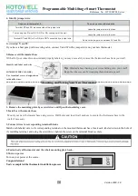
Page 4: ...our wires disconnected and properly labeled you may now safely remove the thermostat base from your wall Mounting and Wiring Your New Thermostat 1 Remove the mounting plate by screw driver and Open th...

Page 5: ...ess to set to set your minute Then press switch to the hour and week day setting respectively press to set the values Programmable Schedule Setting After the above time setting touch the icon each wee...

Page 6: ...ional System 0 Heat Pump System 1 Conventional System 0 Always turn off power at the main power source by removing the fuse or switching the circuit breaker to the off position before installing remov...

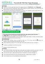
Page 7: ...t your region and type in your phone No or email fig 2 3 then you may get a verification code Type in your password and con rm fig 2 4 to complete your registration If you already have an account plea...

Page 8: ...thermostat can not be connected as above steps please try this AP mode connection process On the thermostat During power off status press and hold the arrow icon for 8 sec until the connecting icon a...

Page 9: ...vice name location create group and etc When thermostat runs in programmable mode click the setting symbol at the bottom of the page to switch to the schedule page where you can simply configure the w...

Page 10: ...time Method 1 Click Share with Familay as fig 4 4 Method 2 Click Profile Sent Add Switch on the device Share with New Member Type in the telephone number you would like to share with Method 3 Home pag...

Page 11: ...isplay Check if the terminals between LCD panel and Relay Power Module is loosen 2 Without output but display works Use a new LCD panel or new Relay Power Module for Replacement 3 Room Temp on display...

Reviews: