background image


Programmable Single Stage Thermostat 


Reference  No.:


HTW-ST01-B 


- 2 -

                                                                            Version 2019-1.0                                                                                             

Tip:  Taking  a  picture  with  a  camera  or  smartphone  can  help  you  not  only  remember  how  wires  are  connected  to  the 

terminals, but can also ensure that you label your wires correctly.


********************************Remove Old Thermostat******************************** 

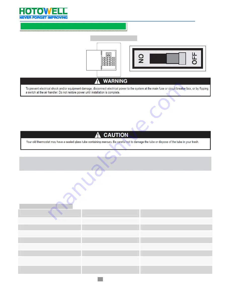
1.Turn Off the Power 


or


To ensure the power to your heating and cooling system has been turned off, try to turn on heating or cooling by changing the 

temperature on your old thermostat


2. Remove the old thermostat cover 

Remove  the  old  thermostat’s  front  cover  from  the  wall  base.  Some  covers  pull  off  easily,  while  others  may  need  to  be 

removed by prying the cover off with a screwdriver.


3. Label wires 

Using your screwdriver, carefully unscrew one wire at a time from the terminal block and attach the corresponding wire label 

sticker. 

Please  note  that  not  all  terminals  may  be  used,  and  that  there’s  no  standard  color  code  for  thermostat  wires,  so  your  wire 

colors may vary.   

For  your  reference,  we’ve  included  a  terminal  label  reference  chart  as  below  to  help  you  connect  the  wires  in  your  old 

thermostat to your new thermostat in case you get stuck. 

Terminal labeling reference chart 

If your current terminal has the following letter


Label the wires with the following letters


Terminal function


RC


RC


24V Power (Cooling)


RH, R, R5, 5


RH


24V Power (Heating)


C


C


24V (Common) from Equipment Transformer


W, W1, 4


W


Heating Relay


Y, Y1


Y


Cooling Relay


G


G


Fan Relay


O


O


Reversing Valve 

(for heat pump applications energized in Cool mode)


B


B


Reversing Valve 

(for heat pump applications energized in Heat mode)


Installation   


Summary of Contents for HTW-ST01-B

Page 1: ...power loss No batteries are required Apply to 24VAC or 2 AA alkaline batteries power supply Air Filter change Indicator Low Battery Indicator Temperature calibration 4 or 5 wire compatible C is optio...

Page 2: ...r screwdriver carefully unscrew one wire at a time from the terminal block and attach the corresponding wire label sticker Please note that not all terminals may be used and that there s no standard c...

Page 3: ...ase from your wall Mounting and Wiring Your New Thermostat 1 Install new thermostat base 2 Connect wires to corresponding terminal blocks Match each labeled wire to it s corresponding terminal on the...

Page 4: ...ition If the heating system has a standing pilot be sure to light it Press to adjust thermostat setting room temperature The heating system should begin to operate Press to adjust temperature setting...

Page 5: ...st the temperature The thermostat will control the room temperature at the selected setting until you press the RUN button to restart the program operation Temperature Override When in the program RUN...

Page 6: ...stem at a 0 5 F 0 5 C differential and SL cycles the system at 1 5 F 1 5 C 2 When operated from batteries only the LCD display backlight will be illuminated less than 5 seconds after each button press...

Page 7: ...to be cooler warmer when the building is vacant or during periods of low activity During early morning hours the need for cooling is usually minimal The time of day clock must be set correctly in orde...

Page 8: ...d start time and temperature for RETURN 3 Period and SLEEP 4 Period Press PRGM again and SAT SUN indicating weekend programming parameters setting Repeat step 5 to complete Saturday and Sunday program...

Reviews: