background image


      Smart Wifi Fan Coil Thermostat 


Reference  No.:


HTW-WF06-FC  Series 


- 2 -

                                                                            Version 2018-1.0                                                                                             


Power Supply 

95~240Vac, 50/60Hz 

Sensor 

NTC3950, 10K 

Current Load 

Fan Relay 5A

(3A-inductive)


Temperature Accuracy 

±

0.5°C or 

±

1


Valve Relay 3A

(1A-inductive)


Set-Point Range 

5~35°C 

Storage Temp. 

-5 ~ 45 °C 

Display Temp. Range 

5 ~ 99°C 

Power Consumption 

< 1.5W 

Timing Error   

< 1% 

Housing Material 

PC +ABS ( Fireproof) 

Installation Box 

EU or Standard Electric Box 

Wires on Terminals 

Wire 2 x 1.5 mm

2

 or 1 x 2.5 mm

2


Protection Class 

IP20 

Operating Buttons 

Capacitive Touch Buttons 


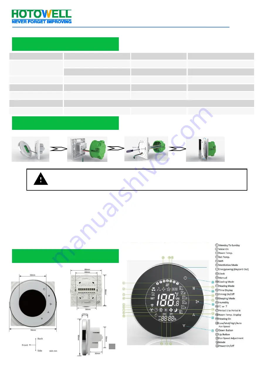
Make sure the power is OFF! Try turning ON your heating/cooling system by changing the temperature. If 
you can’t get the system to turn ON in 5 minutes, you’ll know the power is OFF. 


Take off the installation faceplate by rotating and gently pulling, then connect voltage supply/load 
output/external sensor(if with) wires respectively to appropriate terminals. 


Fix the installation plate onto the electric junction box with screws packed in the box. 


Fasten the thermostat display part and the installation faceplate through the groove.(Installation process 
completed) 


WARNING:      RISK  OF  ELECTRICAL  SHOCK.

  Disconnect  power  supply  before  making  electrical  connection.  Contact 

with  components  carrying  hazardous  voltage  can  cause  electrical  shock  and  may  result  in  severe  personal  injury  or 

death. 

Dimensions and Display 

Specification 

Installation 

Summary of Contents for HTW-WF06-FC Series

Page 1: ... with Amazon Echo Google Home Tmall Genie IFTTT Group Control in 1 App Fashion Sense of Science and Technology Ordering Information HTW WF06 FC 2 2 pipe tube system W Window Card input Smart Wifi Fan Coil Thermostat 4 4 pipe tube system T Clock M Modulating output P Programmable N Modbus RTU communication E External Temperature Sensor K Key Card occupancy input 24v Power Supply with 24Vac e g HTW ...

Page 2: ...heating cooling system by changing the temperature If you can t get the system to turn ON in 5 minutes you ll know the power is OFF Take off the installation faceplate by rotating and gently pulling then connect voltage supply load output external sensor if with wires respectively to appropriate terminals Fix the installation plate onto the electric junction box with screws packed in the box Faste...

Page 3: ... switch to next relevant parameter setting 3 Touch the icon M again to set the weekday schedule settings appear 1 2 3 4 5 will show along the top of the screen Likewise use and M becomingly to adjust the time temperature for the 1 6 period per day Repeat the above process to set the weekend schedule Press M once more to confirm and exit Ex factory Default Settings Time display WEEKDAY MON FRI WEEK...

Page 4: ...t the fan turns to low 00 3 Keypad Lock type 00 All buttons will lock except the Power button 01 All buttons will lock 01 4 Heating Cooling 00 Cool only 01 Heating and Cooling 01 5 Min set point limit 5 C 15 C 05 6 Max set point limit 15 C 45 C 35 7 12 24 hours format 00 12h 01 24h 01 8 Temperature Display 00 display both set point and room temp 01 display set point only 00 9 Economy Mode 00 Norma...

Page 5: ...our region and type in your phone No or email fig 2 3 then you may get a verification code Type in your password and confirm fig 2 4 to complete your registration If you already have an account please just log in On the thermostat During power off status press and hold the arrow icon for 8 sec until the connecting icon appears on the thermostat screen and flashes once a sec Wifi Connection Step 1 D...

Page 6: ...hermostat can not be connected as above steps please try this AP mode connection process On the thermostat During power off status press and hold the arrow icon for 8 sec until the connecting icon appears on the thermostat screen and flashes once a sec press and hold the arrow icon for 8 sec again the icon will flash once per 3 sec fig 4 1 indicates connecting from normal router mode Indicates con...

Page 7: ...s in Manual Mode Thermostat runs in Programmable Mode System in Cooling Mode System in Heating Mode System in Ventilation Mode Fan Speed Indicator When thermostat runs in programmable mode click the schedule setting to switch to the schedule page where you can simply configure the weekly programmable 5 2 schedule up to 6 period each day Workdays Monday Friday Weekend Saturday and Sunday Click Comp...

Page 8: ...ime Method 1 Click Share with Familay as fig 4 4 Method 2 Click Profile Sent Add Switch on the device Share with New Member Type in the telephone number you would like to share with Method 3 Home page of the device Menu as fig 6 1 Device Sharing Add Type in the telephone number you would like to share with Click Profile Integration Select amazon echo Google Home IFTTT Use Now Details as below fig ...

Page 9: ...ay Check if the terminals between LCD panel and Relay Power Module is loosen 2 Without output but display works Use a new LCD panel or new Relay Power Module for Replacement 3 Room Temp on display is not correct Do temperature calibration in parameter in ISU 4 Heating system does not respond Set the mode to heating by press ing the M button Make sure the temperature is set above the room temperatu...

Reviews: