background image

GB

27

PLEASE PHONE US TO REGISTER YOUR APPLIANCE  AND ACTIVATE YOUR PARTS GUARANTEE ON 08448 24 24 24

Installation

Electrical Requirements

For your own safety, we recommend that your cooker
is installed by a competent person such as one who
is registered with NICEIC (National Inspection
Council for Electrical Installation Contracting). The
cooker should be installed in accordance with the
latest edition of the IEE Regulations.

Warning: This appliance must be earthed.

Electrical Connections

The installer must check that the voltage shown on
the rating plate corresponds with the house
electricity supply. The cooker must be supplied via
a suitable double pole isolating switch, having a
contact separation of at least 3mm in all poles
placed in a readily accessible position adjacent to
the cooker. If the cooker is to be wired into a
connector unit, this may be positioned behind the
cooker providing the following requirements are met:
i) The connector unit must not project from the wall

more than 25mm.

ii) The top of the connector must not be more than

130mm above floor level.

Remove the terminal cover at the rear base of the
cooker. Pass the cable through the cable clamp and
connect to the appropriate terminals provided.
Allow sufficient cable for any future servicing.
Tighten the screws on the cable clamp and replace
the cover. Make main connections in the connector
unit or cooker control unit. This appliance conforms
to B.S. EN 55014 regarding suppression of Radio
and Television reception interference.
A double Pole control switch having a minimum
rating of 32 amps should be used to feed the cooker
using a suitably rated cable. Where a hob is fitted
adjacent to or over the cooker, a 45 amp Double
Pole control switch should be used to feed both
units via separate suitably rated cables.
We recommend a minimum of 4mm2 PVC insulated
twin and earth cable conforming to B.S. 6004 for
connection of each appliance.

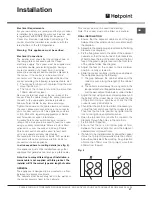
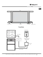
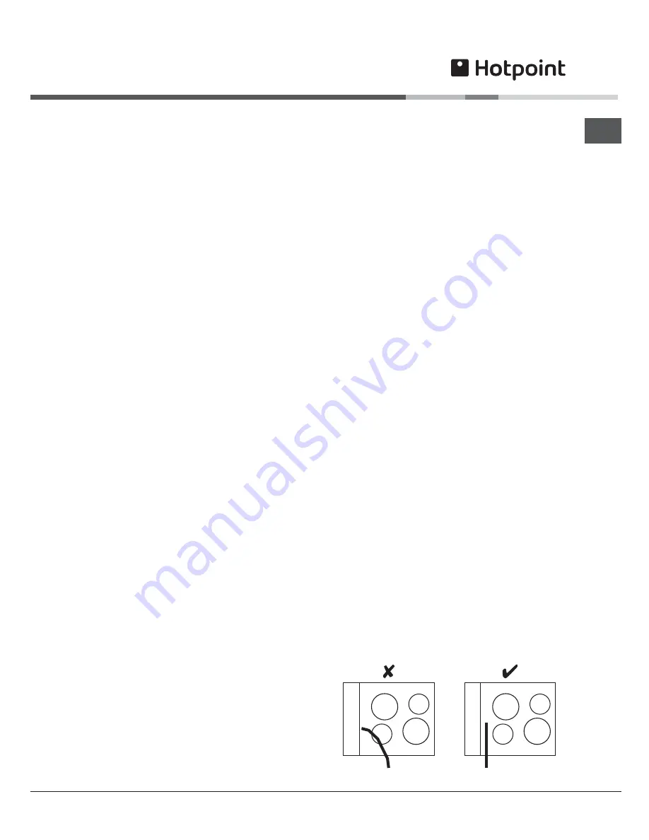
In all cases adhere to routing details (see fig. 5).

This appliance must not be installed over any other
appliance that generates heat such as a plinth heater.

Note: Due to many different types of installation, a
mains cable is not supplied with this product. The
installer will fit the correct type and length of cable.

GENERAL

The appliance is designed to be mounted on a floor
between two adjacent cabinets.
The cabinets must be securely fixed to the wall and
the cooker securely fixed to the cabinets.

This cooker must not be used free standing.
Note; This cooker must not be fitted on a platform.

FINAL INSTALLATION

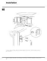
a. Ensure that the adjacent cabinets and the gap

between them have dimensions in accordance with

the diagram.

b. Assemble the plastic plugs provided into the fixing

brackets. See diagram.

c. Fix the fixing brackets to the sides of the adjacent

cabinets so that the centre line of the brackets are
570mm above the top of the plinth line and the front

face of the plastic plug is level with the front face
of the cabinet sides. See diagram.

d. Adjust the feet on the cooker to their minimum

position, i.e. fully screwed in.

e. Slide the cooker centrally into the space between

the cabinets ensuring the following:

i) The gap between the cabinet sides and the

cooker is even along the length of the cabinet

sides.

ii) The cable is routed away from any vents in the

rear panel and is not trapped between the cooker
and the wall, adjacent cabinets or under the feet

f. Adjust the feet using an open ended spanner until

the bottom of the cooker door is in line with the top

of the plinth. Using a spirit level, check that the
cooker is level in all directions.

g. Check that the plinth can be fitted. If necessary re

- adjust the feet and check that the cooker is level.

Then lock the feet into position by tightening the
lock nut using an open ended spanner.

h. Open the top oven door and fix the cooker to the

brackets through the holes in the side trims.

i. Fix the plinth in position.
j. Ensure that there is a minimum gap of 1mm

between the cooker side trim and the adjacent
cabinet doors or drawer fronts.

k. If a hob is to be installed directly above the cooker

it must not project downwards more than 20mm

below the underside of the work top. Any projection
of more than 10mm must not project more than

500mm from the wall.

Fig. 5

Summary of Contents for AHP37X

Page 1: ...ersion Chart 17 Oven Temperature Chart Meat 18 Oven Temperature Charts Baking 19 Main Oven Circulaire Roasting UQ47I 2 UE47X 2 AHP37X 1 UX537CX UBS 537 CX 20 Main Oven Circulaire Roasting Chart UQ47I...

Page 2: ...open a window or use an extractor fan and that persons who may be sensitive to the odour avoid any fumes It is suggested that any pets be removed from the room until the smell has ceased This odour i...

Page 3: ...understand the hazards involved Children shall not play with the appliance Cleaning and user maintenance shall not be made by children without supervision During use the appliance becomes hot Care sho...

Page 4: ...N WITH A FIRE BLANKET OR DAMP CLOTH this will smother the flames and extinguish the fire 3 LEAVE THE PAN TO COOL FOR AT LEAST 60 MINUTES BEFORE MOVING IT Injuries are often caused by picking up a hot...

Page 5: ...EN LIGHT OVEN SHELF DOOR SWITCH MAIN OVEN DOOR INNER DOOR GLASS GRILL PAN FOOD SUPPORT ANTI SPLASH TRAY TOP OVEN DOOR MODEL SERIAL NUMBER LABEL Record the Model No and the Serial No on back page GRILL...

Page 6: ...SHELF DOOR SWITCH MAIN OVEN DOOR INNER DOOR GLASS GRILL PAN FOOD SUPPORT ANTI SPLASH TRAY TOP OVEN DOOR MODEL SERIAL NUMBER LABEL Record the Model No and the Serial No on back page GRILL SETTING CONT...

Page 7: ...grill control is used and after a short period of time when the ovens are used Note Whenever the appliance has been used the cooling fan may run on or restart itself after all the controls have been t...

Page 8: ...activated Programming cooking A cooking mode must be selected before programming can take place Programming the cooking duration 1 Press the button several times until the icon and the three digits o...

Page 9: ...Leave the control at 4 or MAX for toast and Leave the control at 4 or MAX for toast and Leave the control at 4 or MAX for toast and for fast cooking of foods for fast cooking of foods for fast cooking...

Page 10: ...or anti clockwise for HALF grill to select the Grill Setting MIN MAX or 1 4 Grill Controls Example or High Grill Setting NOTE Do not grill with the grill top oven door closed Step 3 After use turn th...

Page 11: ...is still on Turn off at the control and allow to cool before cleaning Care must be taken to ensure the grill mesh is not distorted do not store the grill pan handle on the food grid when the shelf is...

Page 12: ...ve As a guide the front of the utensil should be approx 100mm 4 from the front of the shelf Note Charts are a guide only to suit personal taste and requirements it may be necessary to increase or decr...

Page 13: ...nd on during cooking as the oven thermostat maintains the correct tempera ture Step 4 Place the food on the shelf directly below the element ensuring the oven door is closed NOTE At the end of your co...

Page 14: ...E DEEP TRAY SHOULD BE USED ONLY THE DEEP TRAY SHOULD BE USED ONLY ON THE 2nd AND THE 3rd LEVEL ON THE 2nd AND THE 3rd LEVEL ON THE 2nd AND THE 3rd LEVEL ON THE 2nd AND THE 3rd LEVEL ON THE 2nd AND THE...

Page 15: ...gh Foods ideally suited to defrosting using the fan only setting are cream cream cakes butter cream filled cakes gateaux cheese cakes iced cakes quiches pastries biscuits bread croissants fruit and ma...

Page 16: ...W COOKING 1 Make sure that the dishes to be used will fit into the oven ensuring enough room for air to circulate 2 All dishes cooked on the slow setting will require a minimum of 6 hours however if t...

Page 17: ...TER YOUR APPLIANCE AND ACTIVATE YOUR PARTS GUARANTEE ON 08448 24 24 24 Temperature Conversion Chart 250 120 100 1 275 140 120 2 300 150 130 3 325 160 140 4 350 180 160 5 375 190 170 6 400 200 180 7 42...

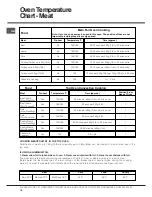
Page 18: ...450g 1lb 35 mins over 1 Beef Lamb Foil Covered Yes 180 190 35 mins per 450g 1lb 1 Pork Slow Roasting Yes 170 180 40 mins per 450g 1lb 40 mins over 1 Pork Foil Covered Yes 190 200 40 mins per 450g 1lb...

Page 19: ...ngues No 80 90 180 240 mins Oven Temperature Charts Baking Baking Top Oven Convection Cooking oo e 6eat Te pe at e C Ti e in in 7 o ition o Ba e o Oven Scones Yes 210 220 10 15 mins 3 Small Cakes Yes...

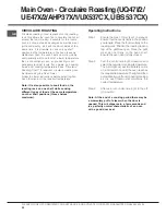
Page 20: ...ven function and the required temperature Note It is also possible to cook food on the roasting rack on one shelf while cooking different types of food at the same temperature on other shelf positions...

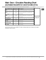
Page 21: ...nutes per 450g 1lb 20 minutes extra 0R Pork any type of joint Pork Chops 160 180 170 25 minutes per 450g 1lb 25 minutes extra 30 45 minutes 5 Lamb any type of joint Lamb Chops 160 180 170 25 minutes p...

Page 22: ...ine and sugar Remember when using a food mixer or processor not to over cream soft margarine Over undercooking Refer to the cooking times and temperatures given in the Oven Temperature Charts provided...

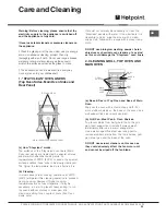
Page 23: ...ill permit this cleaning operation to proceed during cooking However if higher cooking temperatures are not used regularly it may be necessary in order to prevent heavy soiling to run the ovens withou...

Page 24: ...VEN LAMP Warning To avoid electric shocks please ensure that the electricity supply to the appliance is switched off and the appliance is fully cold before cleaning lamp lens Open the oven door and re...

Page 25: ...rop down doors except take care to support the weight of the inner glass when removing and refitting DROP DOWN DOORS Remove the door inner glass as follows 1 Open the door fully and unscrew the two sc...

Page 26: ...in door weight Clean the glass as described above 3 The inside of the outer door glass can now be cleaned while still fitted to the cooker NEVER OPERATE THE COOKER WITHOUT THE INNER DOOR GLASS IN POSI...

Page 27: ...her appliance that generates heat such as a plinth heater Note Due to many different types of installation a mains cable is not supplied with this product The installer will fit the correct type and l...

Page 28: ...PARTS GUARANTEE ON 08448 24 24 24 Installation 890mm Max 870mm Min 597mm min 720mm min 150mm min 170mm max 570mm to top of plinth 570 min 570mm A minimum distance of 25mm should be maintained between...

Page 29: ...YOUR PARTS GUARANTEE ON 08448 24 24 24 Wall Fixing Bracket Cabinet Doors Cooker 2 5mm heat resistant cable to BS 6141 Table 15 Cable size to suit current rating of appliance s Hob Cable Double pole co...

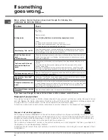
Page 30: ...mber Cook Period is the actual length of time for which the timer will switch the oven s on as part of an Auto Cooking programme Draught from beneath control panel A gentle flow of air will be blown f...

Page 31: ...resulting from transportation improper use neglect or interference or as a result of improper installation Replacement of any consumable item or accessory These include but are not limited to plugs c...

Page 32: ...pply a full range of genuine replacement parts as well as accessory products that protect and hygienically clean your appliance to keep it looking good and functioning efficiently throughout its life...

Reviews: