background image

5

GB

INSTALLATION

Wall drilling and bracket fixing

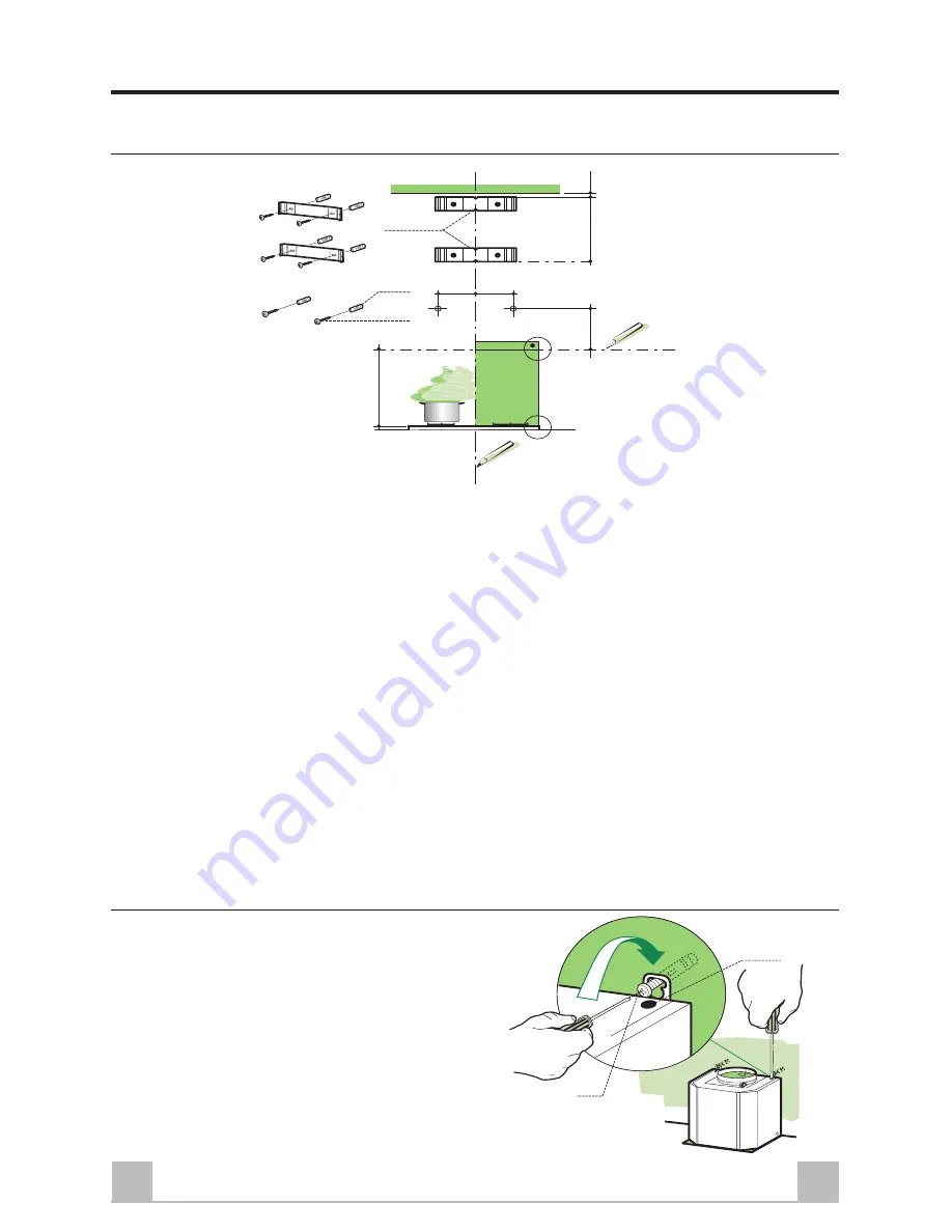
Wall marking:
• Draw a vertical line on the supporting wall up to the ceiling, or as high as practical, at the centre

of the area in which the hood will be installed.

• Draw a horizontal line at 650 mm above the hob.
• Place bracket 

7.2.1

 on the wall as shown about 1-2 mm from the ceiling or upper limit aligning the

centre (notch) with the vertical reference line.

• Mark the wall at the centres of the holes in the bracket.
• Place bracket 

7.2.1

 on the wall as shown at X mm below the first bracket (X = height of the upper

chimney section supplied), aligning the centre (notch) with the vertical line (see diagram above).

• Mark the wall at the centres of the holes in the bracket.
• Mark a reference point as indicated at 116 mm from the vertical reference line and 323 mm above

the horizontal reference line.

• Repeat this operation on the other side.
• Drill ø 8 mm holes at all the centre points marked.
• Insert the wall plugs 

11

 in the holes.

• Fix the brackets using the 

12a

 screws (4,2 x 44,4) supplied.

• Insert the two screws 

12a

 (4,2 x 44,4) supplied in the hood body fixing holes, leaving a gap of 5-

6 mm between the wall and the head of the screw.

Mounting the hood body

• Before attaching the hood body, tighten the two

screws 

Vr

 located on the hood body mounting

points.

• Hook the hood body onto the screws 

12a

• Fully tighten support screws 

12a

• Adjust screws 

Vr

 to level the hood body.

11

12a

323

X

116

1÷2

116

650 min.

7.2.1

12a

Vr

Summary of Contents for HD90X

Page 1: ...Instructions for Installation and Use Electric Hood Model HD90X ...

Page 2: ...mportant details on the safe and proper use of the appliance If you sell or pass the appliance to someone else or move house and leave it behind make sure this Book is also provided so the new owner can become familiar with the appliance and safety warnings If the Book is lost or damaged a copy may be obtained from GDA LTD Morley Way Peterborough PE2 9JB CE marking certifies that this appliance co...

Page 3: ... Do not connect the extractor hood to exhaust ducts carrying combustion fumes boilers fireplaces etc If the extractor is used in conjunction with non electrical appliances e g gas burning appliances a sufficient degree of ventilation must be guaranteed in the room in order to prevent the backflow of exhaust gas The kitchen must have a suitable vent to the outside of the building so that clear fres...

Page 4: ...n 9 1 Reducer Flange ø 150 120 mm 14 1 2 Air Outlet Connection Extension 15 1 Air Outlet Connection Ref Q ty Installation Components 7 2 1 2 Upper Chimney Section Fixing Brackets 11 6 Wall Plugs 12a 6 Screws 4 2 x 44 4 12b 4 Screws 3 5 12e 6 Screws 2 9 x 9 5 Q ty Documentation 1 Instruction Manual 900 500 358 478 37 320 760 760 min 1160 max 478 358 14 1 15 1 7 2 1 12a 11 2 1 2 2 2 12e 12a 11 12b 9...

Page 5: ...tical line see diagram above Mark the wall at the centres of the holes in the bracket Mark a reference point as indicated at 116 mm from the vertical reference line and 323 mm above the horizontal reference line Repeat this operation on the other side Drill ø 8 mm holes at all the centre points marked Insert the wall plugs 11 in the holes Fix the brackets using the 12a screws 4 2 x 44 4 supplied I...

Page 6: ...ng the ducted version connect the hood to the chimney using either a flexible or rigid pipe ø 150 or 120 mm the choice of which is left to the installer To install a ø 120 mm air exhaust connection insert the reducer flange 9 on the hood body outlet Fix the pipe in position using sufficient pipe clamps not supplied Remove any activated charcoal filters RECIRCULATION VERSION AIR OUTLET Push the con...

Page 7: ...ws The wire which is green and yellow must be connected to the terminal in the plug which is marked with the letter E or by the earth symbol or coloured green or green and yellow The wire which is coloured blue must be connected to the terminal which is marked with the N or coloured black The wire which is coloured brown must be connected to the terminal which is marked with the letter L or colour...

Page 8: ...s V2 Speed Reduces the operating speed V3 Speed Increases the operating speed V4 Intensive Maximum speed used for eliminating the highest cooking vapour emission speed Switches off automatically after 10 minutes operation Can also be switched off manually by pressing the button V4 V3 V2 V1 L A Air Outlet B Lights Halogen C Controls D Grease Filters A B C D WARNING Children should not be allowed to...

Page 9: ...emove the metal grease filters Remove the saturated activated carbon filter by releasing the fixing hooks Dispose of the carbon filter Fit the new filter by hooking it into its housing Replace the metal grease filters LIGHT REPLACEMENT 20W halogen bulb Remove the two screws fixing the lighting support and pull it out of from the Hood Remove the bulb from the support Replace with another of the sam...

Page 10: ...s All repairs include a parts and labour guarantee for 12 months from the date of the repair If you require any information or have any questions about your appliance our operators are on hand with help and advice All this ensures that you will receive the best available after sales service possible Extended Warranties UK 08709 088 088 www theservicecentre co uk Republic of Ireland 1850 502 200 Wh...

Page 11: ...and and is subject to the following provisions that your appliance l Has been installed and used correctly in accordance with this instruction booklet l Has been used solely for domestic purposes and is located on domestic premises ie not for commercial or trade use l Has been properly connected to a suitable electrical supply voltage as stated on the appliance rating plate l Has not been subject ...

Page 12: ... co uk Republic of Ireland 1850 302 200 Note Our operators will require the following information Model number Serial number Extended Warranties UK 08709 088 088 Open 8 to 8 Mon Sun www theservicecentre co uk Republic of Ireland 1850 502 200 Genuine Parts and Accessories UK 08709 077 077 Open 8 30 to 5 30 Mon Fri 9 to 12 Sat www theservicecentre co uk Republic of Ireland 01 842 6836 General Domest...

Reviews: