background image

13 of 49

Service Manual UK

Indesit

Company

English

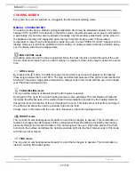
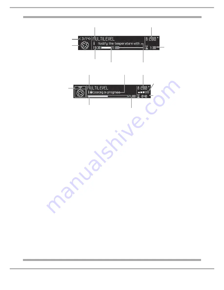
Display

S

elected menu

indicator

TIME

indicator

END
OF


COOKNG


TIME

indicator

Suggests a course of action
or displays the activity currently
being performed by the oven

Selected cooking mode icon /

recommended rack position icon

Cooking mode number indicator

T

emperature

indicator

COOKING


DURATION

indicator

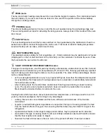
Display in cooking mode

S

elected menu

indicator

C

ooking progress

indicator

END

OF


COOKNG


TIME

indicator

Suggests a course of action or

displays the activity currently

being performed by the oven

Animated

cooking icon

T

emperature

indicator

COOKING
DURATION

indicator

P

reheating 

/


R

esidual heat 

indicators

Summary of Contents for SX1046LPX

Page 1: ...ce Information HOTPOINT MONO CONTROL ELECTRONIC MULTIFUNCTION PYROLYTIC BUILT IN SINGLE OVENS with LED DOOR LIGHTING Models Comm Covered Code SX1046LPX 77138 SX1046LPXS 80824 SX1046SLPX 82495 SX1046SL...

Page 2: ...od Centres etc checks must be made for leaks from seals gaskets and pipe work and rectification carried out where necessary 7 It can be dangerous to attempt DIY repairs maintenance on complex equipmen...

Page 3: ...Modes 20 24 Programming Cooking 25 Practical Cooking Advice 26 Cooking Advice Tables 27 28 Care Cleaning 29 30 Automatic Cleaning using the Pyrolytic Cycle 31 32 Troubleshooting 32 Oven Temperature Te...

Page 4: ...ature control Fast Clean pyrolytic cycle full door seal halogen oven lamp LED door lighting and triple glazed door Model Comm Code Colour First Produced SX1046LPX 77138 Stainless Steel October 2011 SX...

Page 5: ...e 56880 Oven Fan PLASET Type 67190 30W or FIME Model A15 R002 20W Door Lock ITW DL 4705 T105 Earthing Requirement These ovens MUST be Earthed Approvals 2006 95 EC of 12 12 06 Low Voltage and subsequen...

Page 6: ...ectrical Appliances The European Directive 2002 96 EC on Waste Electrical and Electronic Equipment WEEE requires that old household electrical appliances must not be disposed of in the normal unsorted...

Page 7: ...n opening the door to allow any build up of steam or heat to disperse Use dry good quality oven gloves when removing items Take care to avoid heat steam burns when operating the controls Switch off th...

Page 8: ...Important The power supply to the appliance must be cut off disconnected before any adjustments or maintenance work is done on it INSTALLATION OF BUILT IN OVENS In order to ensure that the built in a...

Page 9: ...cabinets with a veneer exterior must be assembled with glues which can withstand temperatures of up to 100 C In compliance with current safety standards contact with the electrical parts of the oven m...

Page 10: ...g the following colour scheme Blue N Brown L Yellow Green Fasten the power supply cable in the corresponding cable clamp and close the cover Electrical Connection Voltage Frequency 230 V 1 N 50Hz Supp...

Page 11: ...to terminal marked E or 6 or coloured Green or Green Yellow Connect Brown wire to terminal marked L or coloured Red Connect Blue wire to terminal marked N or coloured Black If a 13 amp plug BS 1363 is...

Page 12: ...tion 5 MANUAL COOKING MODES icon SETTINGS icon CONFIRM SETTINGS icon TIME icon MINUTE MINDER icon Display DOOR CONTROL PANEL LOCK icon AUTOMATIC COOKING MODES icon SELECTOR control dial CONTROL PANEL...

Page 13: ...ooking mode icon recommended rack position icon Cooking mode number indicator Temperature indicator COOKING DURATION indicator Display in cooking mode Selected menu indicator Cooking progress indicato...

Page 14: ...the movement through with his her hand To use the system correctly before closing the door Open the door fully Do not force the closing movement manually The shelves may have safety stops fitted to st...

Page 15: ...k The door and control panel can be locked while the oven is off once cooking has started or finished and during programming The door control panel lock can be used to lock the oven door and or contro...

Page 16: ...the desired time using the control dial 3 Once you have reached the desired value press the icon again When the oven is switched off the countdown appears on the display When the oven is on the lit s...

Page 17: ...inserting the shelf make sure that the back stop is at the rear of the cavity Cooling Ventilation In order to cool down the external temperature of the oven a cooling fan blows a stream of air between...

Page 18: ...ns are pressed for 30 minutes and the control panel door lock has not been activated the appliance automatically reverts to stand by mode The ECO Mode symbol appears on the display to indicate stand b...

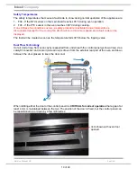
Page 19: ...d a fault code will be displayed The fault will be cleared a soon as the temperature falls 30 C below the tripping value Dual Flow Technology Hot air red arrow from oven cavity is expelled from undern...

Page 20: ...en 50 and 100 The high and direct temperature of the grill is recommended for food which requires a high surface temperature Always cook in this mode with the oven door closed see Practical Cooking Ad...

Page 21: ...temperatures 75 85 and 110 C thereby guaranteeing a perfect level of cooking and enhancing the taste as much as possible The value of these advantages should not be underestimated as the cooking temp...

Page 22: ...con SX1046SLP0X only AUTOMATIC COOKING MODES The temperature and the cooking duration are pre set values guaranteeing a perfect result every time automatically These values are set using the C O P Pro...

Page 23: ...PAPILLOTE mode Use this function to cook whole fish with a maximum weight of 1 kg The paper foil package can be placed directly on the dripping pan Place the food inside the oven while it is still co...

Page 24: ...ted Position the deep dripping pan on shelf level 1 if supplied as an accessory or place the rack on shelf level 1 and stand a dish measuring approximately 35 x 30cm height 5 cm on it the dripping pan...

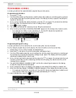
Page 25: ...the correct time 1 Follow steps 1 to 3 to set the duration as detailed above 2 Press the icon twice the end of cooking time will begin to flash 3 Turn the control dial to adjust the end of cooking ti...

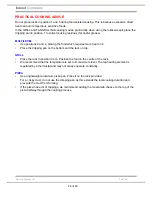
Page 26: ...res more heat on 2 Place the dripping pan on the bottom and the rack on top GRILL Place the rack in position 3 or 4 Position the food in the centre of the rack We recommend that the temperature is set...

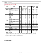
Page 27: ...300 300 300 300 10 20 10 15 10 15 10 15 15 20 10 20 10 20 10 12 3 5 70 80 70 80 Fan grilling Grilled chicken Cuttlefish Spit roast chicken using rotisserie spit where present Spit roast duck using ro...

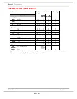
Page 28: ...5 2 or 3 2 or 3 2 2 no no Tarts Tarts 0 5 2 or 3 2 no Shortcrust tarts Apple flan 0 5 2 or 3 2 no Brioche Desserts made with natural yeast brioches almond cake etc 0 7 2 or 3 2 no Cake Desserts made...

Page 29: ...After cleaning rinse and dry thoroughly Do not use abrasive powders or corrosive substances The inside of the oven should ideally be cleaned after each use while it is still lukewarm Use hot water and...

Page 30: ...prise off one of the metal securing clips and remove the glass cover of the lamp holder 2 Remove the light bulb and replace it with a similar one halogen lamp voltage 230 V wattage 25 W cap G 9 3 Repl...

Page 31: ...rol dial select PYROLYTIC and press 4 The appliance suggests a NORMAL pyrolytic cycle with a duration of 1 hour 30 minutes Other levels of cleaning may be selected Use the control dial to select one o...

Page 32: ...cooled down completely Alternatively you can make use of the already heated oven in which case it is not necessary to remove the deposits they are completely harmless and will not affect your food in...

Page 33: ...he thermocouple junction is positioned as near to the centre of the gate as possible See Fig 7 3 Position the gate on the centre of the rod shelf so that the large plates on the gate are facing the di...

Page 34: ...E LIMITS Mean Oven Centre Temperature Limits All appliances Upper Limit M O C T 215 C Thermostat accuracy 15 C Lower Limit M O C T 185 C Maximum Differential of Overshoot and Undershoot Conventional M...

Page 35: ...circuit Triac open or relay not closing 59h Ceiling heating element circuit Triac open or relay not closing 61h Floor heating element feedback failure 62h Circular heating element feedback failure 63h...

Page 36: ...tors on component and board sides 4 Check the state of cables 5 Replace the Main PCB F6 01 Temperature too high in the Main Top cavity 1 Check PTC probe is con gured properly 2 Replace the Main PCB F7...

Page 37: ...ng properly 2 Check connectors on component and board sides 3 Check the state of cables 4 Replace the Main PCB F17 01 G r i l l 1 h e a t i n g e l e m e n t D I S C O N N E C T E D o r INTERRUPTED he...

Page 38: ...isconnected 73h Tangential fan circuit open 74h Tangential fan FB failure 75h Tangential fan general failure 76h Tangential fan in diode mode master relay jammed 81h Circular fan in diode mode 82h Cir...

Page 39: ...nent Demo Always start with the appliance off The appliance will not enter Demo mode if the language has not been set beforehand To enable Turn and the Start key simultaneously for 10 seconds You will...

Page 40: ...en PTC probes and main NTC PCB checked 3 For 5 seconds Tangential Fan ON and door blocked where there is a door lock 4 For 5 seconds Tangential Fan ON Spit Roast where present and door lock released w...

Page 41: ...V 12V 12V VCC2 VCC POT1 POT2 GND GND INTERNAL FAN LAMP 1 TANG LAMP 2 MG 12V LEVEL SENSOR 12V MANIGLIA SDA SCL GND 12V SDA SCL GND 12V SWITCH ON OFF 3641 02 k05 v167 3641 07 K30 V167 3550 03 K30 VHR5M...

Page 42: ...off the rubbers side gaskets until the 4 fixing holes are exposed 3 Remove the 4 wood screws securing the oven to the cabinetry 4 On reassembly reposition the 2 gaskets B Top Cover 1 Remove the oven...

Page 43: ...Fig 5 F Display Board 1 Remove the oven from the cabinet A 2 Remove the top cover B 3 Unclip the red display board protector 4 Pull off the control knob 5 Disconnect the wiring to the main power board...

Page 44: ...wer board 6 Remove the 6 screws 3 either side of the oven into the side panels securing the oven cavity cover 7 Remove the door lock as in O 8 Remove the 5 screws which secure the ducting including on...

Page 45: ...on the fan cover in the oven 4 Remove the single nut on the oven fan clockwise thread and remove 5 Remove the 3 screws from the motor from the rear of the cooker not and remove the wiring and replace...

Page 46: ...to lift up the small levers located on the two hinges See Figs 12 and 13 6 Grip the door on the two outer sides and close it approximately half way 7 Pull the door towards you lifting it out of the hi...

Page 47: ...To refit them place in the grooves on the outer door moulding See Figs 14 17 R Door Hinges and Door Handle 1 Remove the inner and centre door glasses Q 2 The screws securing the door hinges and door...

Page 48: ...trical supply the LEDs on the Smart Card Reader will light in this sequence a Red ON Good Communication between Smart Card Reader and Card b Red OFF Green Blinking Download taking place c At end Green...

Page 49: ...imilar to those currently fitted into the SmartCard Reader NOTE The USB Hardware Key also supports a low voltage connection point which allows an external power supply to be connected to the Hardware...

Reviews: