background image

Page 18

ELECTRICAL REQUIREMENTS AND

PRECAUTIONS

Y

our Hot Spring

®

spa has been carefully designed to give you maximum safety against electrical shock. Connecting the spa to an improperly

wired circuit will negate many of the spa’s safety features. Improper wiring may also cause electrocution, risk of fire, and other risks of injuries.

Please read and follow the electrical installation requirements and instructions for your specific spa model completely!

SERVICE NOTE:

All Hot Spring spa models are equipped with a power indicator which, in addition to showing the spa has power to it, has a

diagnostic function as well. It will begin blinking if the heater high-limit thermostat has tripped. If the power indicator light is blinking, follow the
instructions in the Troubleshooting section to identify and correct the cause. The power indicator will stop blinking once the problem has been
corrected.

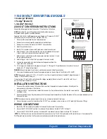
230 VOLT PERMANENTLY CONNECTED MODELS

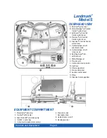
• Landmark

®

(Model S)

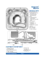
• Vanguard

(Model V)

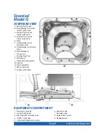
• Grandee

®

(Model G)

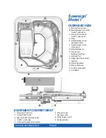
• Sovereign

®

Limited Edition (Model ILE)

HOT SPRING SPAS MUST BE WIRED IN ACCORDANCE WITH ALL APPLICABLE LOCAL ELECTRICAL CODES. ALL ELECTRICAL WORK
SHOULD BE DONE BY AN EXPERIENCED, LICENSED ELECTRICIAN. WE RECOMMEND THE USE OF APPROPRIATE ELECTRICAL CONDUIT,
FITTINGS, AND WIRE FOR ALL CIRCUITS.

An electrical subpanel containing two GFCI breakers is included with each 230 volt spa. We recommend that this subpanel be used to supply
power and protect the spa.

This subpanel requires a 50 amp, single phase, 230 volt, four wire service (two line, one neutral, one ground). The grounding conductor must be at
least the same gauge as the line conductors, but not less than #10 AWG. A minimum #10 AWG solid copper bond wire is also required.

Mount the subpanel in the vicinity of the spa, but not closer than five feet away, in accordance with all local codes. (N.E.C. 680-38 to 41-A-3)

INSTALLATION  INSTRUCTIONS

1. To connect the electrical service, first remove the screws from the equipment compartment door. Carefully pull the door panel away and

down in order to remove it completely from the spa.

2. Locate the IQ 2020

spa control box. Loosen the screws on the front of the control box. Remove the screws and the control box cover.

3. Route the electrical service from the subpanel into the spa equipment compartment. Position the conduit in the recess provided between the

frame and door. Install the supply conduit so as not to block the drain valve. 

NOTE: 

The subpanel must be placed in sight of the spa, at a minimum distance of five feet away.

4. Connect the supply conduit to the bottom of the IQ 2020

spa control box, using a minimum of 3/4” liquid-tight, flex conduit fittings.

WIRING CONNECTIONS

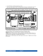
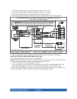
1. Identify the TB-1 terminal block, located inside the IQ 2020

control box at the lower left-hand corner.

2. Connect the #12 AWG, BLUE wire, from the subpanel 20 amp breaker, terminal L1 to TB-1, terminal 2.

3. Connect the #12 AWG, RED wire, from the subpanel 20 amp breaker, terminal L2 to TB-1, terminal 4.

4. Connect the #12 AWG, WHITE wire, from the subpanel 20 amp breaker, terminal N (load neutral) to TB-1, terminal 5.

NOTE:

The WHITE neutral wire must be attached to the LOAD neutral on the 230 volt, 20 amp breaker (not to the neutral bus bar in the subpanel).

The WHITE neutral wire coming from the breaker itself is already connected to the neutral bus bar.

5. Connect the #10 AWG, BLUE wire, from the subpanel 30 amp breaker, terminal L1 to TB-1, terminal 1.

6. Connect the #10 AWG, RED wire, from the subpanel 30 amp breaker, terminal L2 to TB-1, terminal 3.

7. Connect the #10 AWG, GREEN wire, from the subpanel GROUND bar to TB-1, system ground terminal.

8. Using the pressure wire connector provided on the outside of the control box, bond the spa to all exposed metal equipment or fixtures,

handrails, and the concrete pad (if applicable) per N.E.C. Article 680 and local codes.

9. Replace the control box cover and securely tighten the fastening screws. Close and secure the equipment compartment door.

WARNING: FILL THE SPA WITH WATER BEFORE TURNING ON THE POWER.

Once your spa has been filled with water, turn it on and test all of the circuit breakers. 

NOTE:

If both breakers immediately trip, verify that the #12 AWG WHITE neutral wire is connected from TB-1 terminal 5 to the L1 (load neutral)

terminal of the 20 amp subpanel breaker. Each breaker should be tested prior to each use. Here’s how:

Electrical Requirements

Summary of Contents for Grandee

Page 1: ...Owner s Manual Owner s Manual...

Page 2: ...__ TELEPHONE ________________________________________________________________________________________________________________ SPA MODEL SERIAL NUMBER __________________________________________________...

Page 3: ...odel J 33 CONTROL PANEL VIEWS Main Control Panels 34 Control Panels 34 Indicator Lights 34 Locking Features 34 Main Control Panel Buttons and Display 35 Water Care 36 Auxiliary Control Panel 36 115 Vo...

Page 4: ...the unit as needed to comply with local requirements WARNING To reduce the risk of electrical shock replace a damaged cord immediately Failure to do so may result in death or serious personal injury d...
Page 5: ...ection is a shock hazard An extension cord may cause a voltage drop which will cause overheating of the jet pump motor and motor damage Attempt to open the electrical control box There are no user ser...

Page 6: ...before entering the spa to be sure it s comfortable SAFETY SIGN Each Hot Spring spa is shipped with a SAFETY SIGN in the owner s package The sign which is required as a condition of Product Listing s...

Page 7: ...s 620 lbs 281 kg 4 556 lbs 2 067 kg 105 lbs per square foot 115 volt 20 amp Dedicated GFCI protected circuit or 230 volt 50 amp Single phase GFCI protected circuit Prodigy Model H 33 84 m 90 square fe...

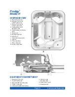
Page 8: ...A O A B E D M F F F G G OVERHEAD VIEW A SmartJet system lever B Moto Massage jet Comfort Control system lever C JetStream jet Comfort Control system lever D Precision jets Comfort Control system leve...

Page 9: ...oothing Seven jets K JetStream jet L Heater return and spa drain M Light lens N Filter compartment O Main control panel P Auxiliary control panel Grandee Model G 1 Wavemaster jet pump 2 No Fault 6000...

Page 10: ...artJet system lever B Moto Massage jet Comfort Control system lever C Precision jets Comfort Control system lever D Pillow E Hydromassage jet with directional nozzle F Hydromassage jet with rotary noz...

Page 11: ...HEAD VIEW A SmartJet system lever B Moto Massage jet Comfort Control system lever C Precision jets Comfort Control system lever D Pillow E Hydromassage jet with directional nozzle F Hydromassage jet w...

Page 12: ...T OVERHEAD VIEW A SmartJet system lever B Moto Massage jet Comfort Control system lever C Precision jets Comfort Control system lever D Pillow E Hydromassage jet with directional nozzle F Hydromassage...

Page 13: ...MENT COMPARTMENT OVERHEAD VIEW A SmartJet system lever B JetStream jet Comfort Control system lever C Precision jets Comfort Control system lever D Hydromassage jet with directional nozzle E Hydromass...

Page 14: ...VIEW A SmartJet system lever B JetStream jet Comfort Control system lever C Moto Massage jet Comfort Control system lever D Precision jets Comfort Control system lever E Pillow F Hydromassage jet wit...

Page 15: ...ntact your local electrical code compliance inspector for more information inspection for proper grounding may be required before pouring concrete to form the slab If you place the spa on the ground e...

Page 16: ...set it aside Carefully remove the shims and keep them together remembering the corner from which each set of shims came 5 With more than one person lifting lift the lowest side of the spa the one wit...

Page 17: ...E All dimensions are approximate measure your spa before making critical design or pathway decisions 15 leveling points place shims approx 18 in from edge then center middle shims U P S I D E D O W N...

Page 18: ...ctions Sovereign Model I ILE Leveling Points NOTE All dimensions are approximate measure your spa before making critical design or pathway decisions 15 leveling points place shims approx 18 in from ed...

Page 19: ...Leveling Points NOTE All dimensions are approximate measure your spa before making critical design or pathway decisions Spa Leveling Instructions 10 leveling points place shims approx 15 in from edge...

Page 20: ...Leveling Points NOTE All dimensions are approximate measure your spa before making critical design or pathway decisions Spa Leveling Instructions 10 leveling points place shims approx 15 in from edge...

Page 21: ...the IQ 2020 spa control box Loosen the screws on the front of the control box Remove the screws and the control box cover 3 Route the electrical service from the subpanel into the spa equipment compar...

Page 22: ...t is essential that you understand and apply these installation requirements Your Hot Spring spa has been carefully engineered to provide maximum safety against electric shock Remember connecting the...
Page 23: ...place the program jumpers as shown in Figure 2 use Watkins P N 36021 NOTE The program jumpers JP 1 JP 2 JP 3 and JP 4 must be set correctly for the spa to operate Disregard jumpers 5 through 10 they...

Page 24: ...e TEST button on each GFCI breaker and observe it click off 2 Wait 30 seconds then push the breaker switch to the OFF down position to ensure that it has completely disengaged then push the breaker sw...

Page 25: ...er cord will come out of the bottom of the equipment compartment door For your safety when the electrician is installing the 20 amp single electrical outlet and waterproof cover outdoors it should be...

Page 26: ...jet pump and offer two jet menus The Landmark Grandee Vanguard and Sovereign Limited Edition are equipped with a No Fault 6000 stainless steel high watt density heater The heating system consists of...

Page 27: ...e that the SmartJet lever is pointing to the 3 o clock position see illustration in SmartJet system section 4 Adjust Total Alkalinity TA to 125 ppm Calcium Hardness CH to 150 ppm then spa water pH to...

Page 28: ...adjusting the mixture of air and water Jets with an adjustable faceplate are controlled by turning the faceplate clockwise for a stronger flow counterclockwise for a softer flow Jets without an adjust...

Page 29: ...feet legs hips and lower back The intensity of the JetStream jets can be altered except the ones found in the FootWell system using only the Comfort Control lever with the steel blue or dark grey lev...

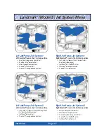
Page 30: ...2 Soothing Seven jets 1 directional hydromassage 1 JetStream jet on right wall 1 DreamJet massage pillow on right front Right Jet Pump Jet System 1 Right SmartJet lever in the 3 o clock position 3 Jet...

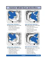
Page 31: ...ll System 2 Precision jets on left seat calf area Right Jet Pump Jet System 2 Right SmartJet lever in the 9 o clock position 1 Moto Massage jet on right rear 4 Precision jets above right Moto Massage...

Page 32: ...Cluster system on right wall 2 dual port rotary 1 directional hydromassage 2 Soothing Seven jets on left wall 2 Precision jets on left rear seat calf area 2 Precision jets on right rear seat calf are...

Page 33: ...o Massage jet 2 JetStream jets in FootWell System 1 directional hydromassage jets on left wall 3 Jet Cluster system on left wall 2 dual port rotary 1 directional hydromassage Jet System 1 SmartJet lev...

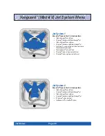
Page 34: ...ecision jets above Moto Massage jet 10 Precision jets on right rear 2 dual port rotary jets on right front 1 JetStream jet in FootWell System Jet System 2 SmartJet lever in the 6 o clock position 1 Mo...

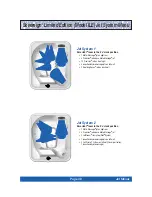
Page 35: ...rear 3 Jet Cluster system on left rear 2 dual port rotary 1 directional hydromassage Jet System 1 SmartJet lever in the 3 o clock position 10 Precision jets on right rear 2 dual port rotary jets on le...

Page 36: ...ll Jet System 2 SmartJet lever in the 9 o clock position 1 Moto Massage jet on left rear 4 Precision jets above Moto Massage jet 2 Stacked hydromassage jets on back wall 1 directional hydromassage 1 d...

Page 37: ...u increase or decrease the temperature setting of the spa the ready indicator will turn off until the spa temperature reaches the acceptable range for the new set temperature Additionally a blinking R...

Page 38: ...e spa press the TEMP plus button The set temperature will be displayed unless the spa is locked in which case the word SPA is displayed with the lock symbol The set temperature display will automatica...

Page 39: ...timer is on When activated the symbol will be visible even in bright light when the main display backlight is off In low light conditions the Summer Mode symbol will only be visible when the display...

Page 40: ...tion pump which can add heat to the water through normal operation heater and ozone if installed will immediately shut down for the next eight hours Additionally the summer mode display on the main co...

Page 41: ...gallon from the bleedline system 6 When empty inspect the spa shell and clean as required Follow the Care of the Exterior Finish instructions 7 Close the drain valve and reinstall the drain cap 8 Rei...

Page 42: ...ng period of time that is during a vacation or if the spa is winterized or when the spa water is being super chlorinated the spa pillows should be removed until the next spa use To remove and replace...

Page 43: ...move tree sap use cigarette lighter fluid not charcoal lighter fluid Use sparingly and rinse with a saddle soap solution immediately afterwards then wipe dry Important reminders DO remove snow buildup...

Page 44: ...andles DO NOT use any chemicals or cleaners except those recommended by Watkins Manufacturing Corporation or its Authorized Sales and Service Dealer DO NOT use hard sharp or metal objects such as a ca...

Page 45: ...y gravitational flow 5 Remove the threaded cap from the secondary drain The remaining water about 1 gallon will drain from the bleedline system 6 Remove the filter cartridges then clean and store the...

Page 46: ...ON THE THREE FUNDAMENTAL AREAS OF WATER MAINTENANCE Water Filtration Chemical Balance pH Control Water Sanitation Water sanitation is the responsibility of the spa owner achieved through the regular a...

Page 47: ...apped oxidizer gas which may exist as a result of the shock treatment not daily sanitation may eventually cause discoloration or vinyl degradation to the bottom of the cover This type of damage is con...

Page 48: ...below 7 are acidic Maintaining the proper pH level is extremely important for Optimizing the effectiveness of the sanitizer Maintaining water that is comfortable for the user Preventing equipment dete...

Page 49: ...dirt detergents algae and chemicals Sodium Dichlor chlorine is the only recommended sanitizer that will work in conjunction with all of the other products in this system FreshWater III high output oz...

Page 50: ...1 1 4 tablespoons Jetsetter Model J 1 tablespoon Add one half 1 2 teaspoon of chlorine per 250 gallons Landmark Model S 1 teaspoon Grandee Model G 1 teaspoon Vanguard Model V 3 4 teaspoon Sovereign Mo...

Page 51: ...circulation pump filter standpipe it is subjected to the continuous flow of water created by the pump s 24 hour circulation The flowing water through a chemical erosion process carries with it the sil...

Page 52: ...cover at least half way to allow the chlorine gas to vent off The high concentration of chlorine gas which may exist as a result of super chlorination not daily sanitation may eventually cause discol...

Page 53: ...eatly enhances the quality of the spa water when used to supplement the spa owner s regular water maintenance program Contrary to some information circulated throughout the pool and spa industry regar...

Page 54: ...STRY QUESTIONS Question Why can t I use a floater to sanitize my spa water Answer Watkins Manufacturing Corporation does not recommend the use of a floater for three reasons 1 The floater is unable to...

Page 55: ...Generally corrosion is caused by low pH or by water with levels of TA CH pH or sanitizer which are outside the recommended ranges DPD The preferred reagent used in test kits to measure the Free Availa...

Page 56: ...CUT OFF The Hot Spring spa No Fault 6000 heater is called the No Fault heater because it comes with an unconditional warranty This means that any failure during the stated warranty period that require...

Page 57: ...ive of Watkins Manufacturing Corporation Alteration shall include any component or plumbing change electrical conversion or the addition of any non approved sanitation or water purification device or...

Page 58: ...ets and light operate Ready indicator is dark Jets weak or surging Light inoperative Power failure GFCI tripped Heater high limit thermostat tripped Spa lock activated Heater thermal cut off tripped C...

Page 59: ...i d g e S o a k F i l t e r C a r t r i d g e S o a k F i l t e r C a r t r i d g e R e s t a i n E v e r w o o d R e s t a i n E v e r w o o d S p a C a b i n e t S p a C a b i n e t C l e a n a n d...

Page 60: ...ER MODEL JC 12 01 2001 Watkins Manufacturing Corporation Hot Spring Built for a lifetime of relaxation Endurol Moto Massage Landmark Grandee Vanguard Sovereign Prodigy Jetsetter Jet Cluster SmartJet C...

Reviews: