14
installation
&
operation
manual
|
oxm
/
ogm
heating
system
5.2.12 HEATING TANK/ELEMENT
WARNING
!
Hazardous voltage:
Before wiring, servicing or cleaning
the heating system, turn off the power and follow your
organization’s lockout and tagout procedure. Failure
to do so could allow others to turn on the power
unexpectedly, resulting in harmful or fatal electrical
shock.
At least once per year, clean the interior of the heating
tank and the heating element with a wire brush and/or
damp cloth. Periodically check the sediment build-up
around the element loops. Any scaling or build-up will
shorten element life.
To replace the heating element or perform routine
maintenance, use the following procedures.
See Fig. 15
.
1.
De-energize the heating system. Allow fluid to cool.
2.
Close isolation valves.
3.
Drain the fluid from the heating tank
(F)
.
4.
Open heating element assembly
(B)
cover.
5.
The wire connections inside the enclosure
correspond to one of the phase configurations
shown on the following page. Note your unit’s
phase configuration.
See Fig. 17
.
OOE:
Replacement elements may be a different
phase configuration.
6.
Disconnect the ground (green/yellow) and power
electrical wires from the posts inside the cap.
7.
Unscrew cable gland
(G)
from heating element
assembly
(B)
.
See Fig. 16
. Remove electrical cable
and wires from the heating element.
8.
Unscrew heating element assembly bolts
(A)
.
Detach heating element assembly (B) from heating
tank flange
(D)
. Remove assembly and heating
elements
(E)
from tank
(F)
.
9.
Replace the heating elements
(E)
or perform the
necessary cleaning procedure. Ensure heating
element gasket
(C)
is in place.
5.2.13 REASSEMBLY OF HEATING
ELEMENT AND TANK
To reassemble the heating element and tank, follow the
steps listed in
SECOIO 5.2.12
in
reverse order
. Make
sure the ground and power electrical wires are properly
reconnected using the provided washers, cup washers
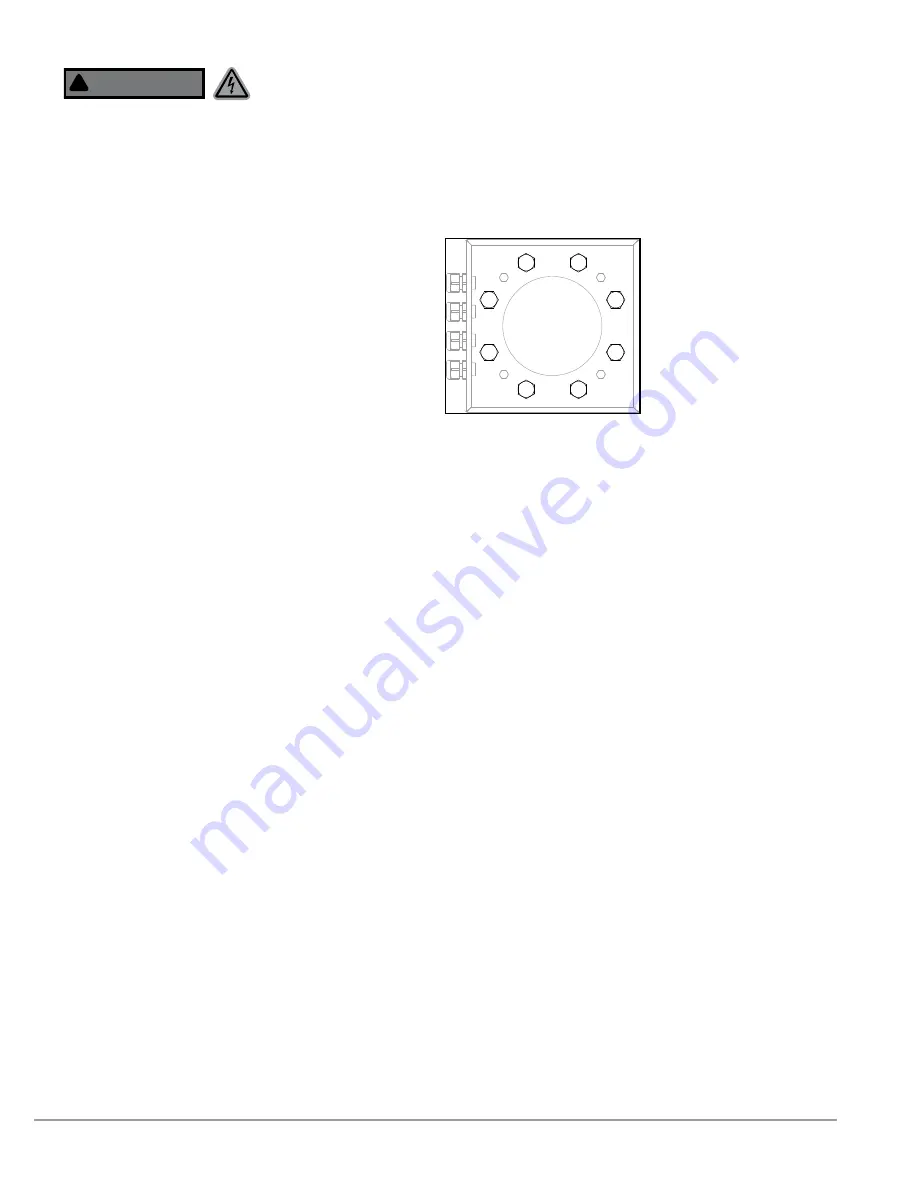
and nuts. Tighten heating assembly bolts
(A)
uniformly,
using pattern shown.
See Fig. 14
. Tighten bolts to snug-
tight plus 30
°
rotation, or 200 lbf · ft (271 N · m)
1
2
3
4
5
6
7
8
Figure 14. Heating assembly
bolts, showing recommended
tightening pattern.


