2.4
MOUNTING
CAUTION
!
Lifting hazard:
Proper rigging and safety equipment
must be used to move this equipment. Do not lift
the heating system by any cords, electrical conduit
or cabling. Create a plan before attempting to move.
Proper lifting locations are identified on each system;
use these locations when lifting and mounting
the system.
Overheating hazard:
When mounting the heating tank,
position the tank so that it is completely full of fluid
while in operation.
NOTICE
Heating system damage:
Engine vibration will
damage the heating system; isolate the heating system
from vibration. Never mount the heating system or
components directly to the engine.
Improper mounting hazard:
Reference heating
system component drawings before mounting the
system. Unless mounted properly, the heating system
will be unstable.
2.4.1 TANK AND PUMP
Mount the heater in a vertical orientation with tank
directly above control box and pump
.
Reference
drawings for mounting position. When installing the
heating system, note that the tank requires a minimum of
30 inches (63.5 cm) of clearance to remove element for
maintenance.
2.5
ELECTRICAL CONNECTIONS
WARNING
!
Hazardous voltage:
Before wiring, servicing or
cleaning the heating system, turn off the power
and follow your organization’s lockout and tagout
procedure. Failure to do so could allow others to turn
on the power unexpectedly, resulting in harmful or
fatal electrical shock. Install in accordance with the
National Electrical Code (NEC) or Canadian Electrical
Code (CEC), and any applicable local codes (such as
NFPA 496), based on the installation location.
Electrical hazard:
The heating system must be
connected to a suitable protective earthing conductor.
The heating system’s power supply must be connected
to a suitable overcurrent limiting device. A means
of disconnection from power supply is required.
HOTSTART recommends that a power switch or
circuit breaker be located near the heating system for
safety and ease of use. Reference markings on heating
system for specific ratings.
Grounding conductor:
Equipment grounding
conductors shall be sized per NEC 2017 Table 250.122
for US installations. For international installations, use
IEC 60079-0, Clause 16. Ground terminal block will
accept 16–4 AWG conductors. External grounding
connection not provided. Metallic conduit or armored
cable must be used. Wiring systems shall comply with
15.1.2 b) of IEC 60079-0.
2.5.1 MAIN POWER SUPPLY
1.
Connect the specified power from the customer-
supplied circuit breaker to the terminal blocks
located in the main control box.
See Fig. 4 and
Table 2.
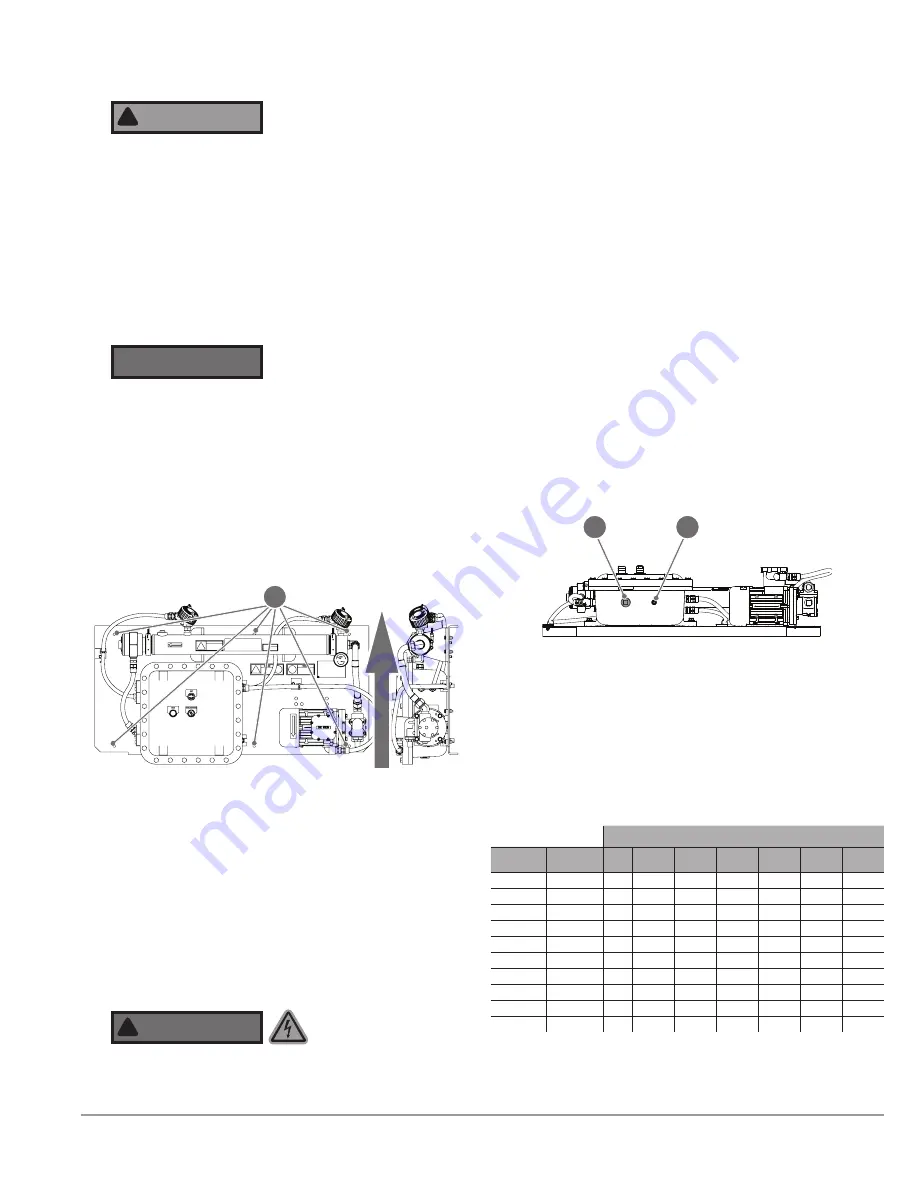
Figure 3.
OLA 0.438 inch (11.13 mm) diameter mounting
holes
×
6
(A)
. Mount unit in orientation shown. Do not mount at an
angle or in any other orientation.
Figure 4.
OLA underside, showing 1.25
″
NPT main power entrance
(A)
and 0.5
″
NPT customer interface wiring entrance
(B)
.
JA
B
A
Copper Wire Stranding Classes – Number of Strands
Wire
Size
Torque Solid Class
B
Class
C
Class
G
Class
H
Class
I
Class
K
2/0 AWG 120 in · lbs
19
37
1/0
120 in · lbs
19
37
1
120 in · lbs
19
37
~133
~259
~210
~836
2
120 in · lbs
7
19
~49
~133
~161
~665
4
120 in · lbs
7
19
~49
~133
~105
~420
6
120 in · lbs
7
19
~49
~133
~63
~266
8
40 in · lbs
7
19
~49
~133
~41
~168
10
35 in · lbs
1
7
19
~27
~104
12
35 in · lbs
1
7
19
~19
~65
14
35 in · lbs
1
7
19
~19
~41
Table 2. Line Side Wire Approvals. ~Qantity of strands for Classes G,
H, I, K may vary by manufacturer. Aluminum stranded wire range: 2/0
–
#6 AWG. Minimum 90 °C wire for all electrical connections.


