


3.3
HEATING SYSTEM START-UP
WARNING
!
Hazardous voltage:
Before wiring, servicing or cleaning
the heating system, turn off the power and follow your
organization’s lockout and tagout procedure. Failure to do
so could allow others to turn on the power unexpectedly,
resulting in harmful or fatal electrical shock.
NOTICE
Pump damage:
Do not run the motor/pump assembly
dry for more than five seconds at a time. Running a
pump that is not completely filled with fluid will cause
damage to the pump seal.
Proper heating operation:
The high-limit temperature
control relay (TCR2) must be set at least 18
°
F (10
°
C)
higher than the control temperature control relay (TCR1)
for proper heating operation. This will prevent nuisance
tripping of the high-limit circuit.
3.3.1 FIRST RUN PROCEDURE
1.
For three-phase applications, ensure a motor
rotation check has been performed prior to
introducing fluid to the pumps (
see
SECOIO
OOE:
Single-phase systems are prewired to
ensure the pump motor rotates in the
correct direction. A motor rotation check is
not necessary.
2.
Check and tighten all electrical and plumbing
connections.
3.
Ensure isolation valves are
open
before energizing
the system.
4.
Bleed all trapped air from the heating system by
opening a plug or pipe fitting at or near the pump.
Press and hold the
prime
button to evacuate any
remaining air in the lines.
OOE:
When priming the pump, the pressure
gauge should indicate an increase in
pressure. Your system’s operating pressure
may vary depending on the configuration
of the engine.
5.
Turn the
local
/
off
/
remote
switch to
local
or
remote
to energize the heating system.
6.
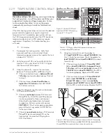
Once operation is satisfactory, turn the control
dial on the temperature control relay TCR1 to
the desired temperature setting for engine oil.
HOTSTART recommends a control temperature on
TCR1 of 104 °F (40 °C). The high-limit temperature
setting on TCR2 should be set at 194 °F (90 °C).
See
SECOIO 3.2.2
and
SECOIO 3.2.3
.
7.
Turn the
local
/
off
/
remote
switch to
remote
to
verify the 24 V DC remote signal connection
(if installed).
4
MAINTENANCE AND
TROUBLESHOOTING
4.1
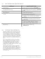
SYSTEM FAULTS
4.1.1 OIL FAULTS
A fault signal will be transmitted if:
•
The oil pump motor protection switch is
tripped (MPS1).
•
The oil high-limit temperature is exceeded
(TCR2).
A failure in the pump motor that causes the motor
protection switch (MPS1) to trip will shut down the
heating system. A fault signal will be transmitted. If this
failure occurs, the
local
/
off
/
remote
switch must be
switched to
off
and the operator must press the
reset
button (or the MPS reset/on button) to reset the fault.
(
See
SECOIO 3.1.3.
)
If there is a failure that causes a high temperature to
occur, the high-limit temperature controller (TCR2) will
shut down the heating system, including the pump
motor. A fault signal will be transmitted. To restart
the system, the
local
/
off
/
remote
switch must be
switched to
off
and then back to
local
or
remote
to resume operation once the fluid temperature drops
below the high-limit preset (
See
SECOIO 3.2.3
.
).
For
additional troubleshooting,
see
SECOIO 4.5
.
4.2
SYSTEM MAINTENANCE
WARNING
!
Hazardous voltage:
Before wiring, servicing or
cleaning the heating system, turn off the power
and follow your organization’s lockout and tagout
procedure. Failure to do so could allow others to turn
on the power unexpectedly, resulting in harmful or
fatal electrical shock.
Instructions for the following maintenance procedures
are provided to ensure trouble-free operation of your
heating system. Replacement parts must meet or exceed
original part requirements in order to maintain the


