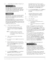
OOE:
The specified power source must be within
plus or minus 10% of the rated voltage.
OOE:
The circuit breaker must be near the
heating system and easily accessible.
HOTSTART recommends connecting the
heating system to a circuit breaker rated for
125% of the system’s maximum load.
OOE:
The main power supply operates the
heating elements and the circulating
pumps. A transformer is used to operate
the control circuit. The transformer and
control circuits are overload-protected.
h
For
three-phase applications
, the terminal
blocks are labeled
L1
,
L2
and
L3
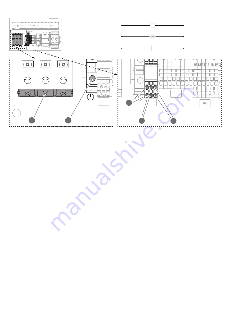
(A)
.
h
For
single-phase applications
, use the terminal
blocks labeled
L1
and
L2
or
L
and
(A)
.
2.
Connect the main power ground wire to the ground
block
(B)
.
2.5.2 CUSTOMER INTERFACE
CONNECTIONS
The following customer interface connections are
available for remote control and monitoring
(See Fig. 5)
:
•
OB2:1/OB2:2
Remote On/Off 24 V DC shutdown (C)
When activated, the remote on/off
connection shuts down the heating system.
When deactivated, normal heating will
resume. Use this connection for remote
operation of the heater when the
local
/
off
/
remote
switch is turned to
remote
.
OOE:
The
24 V DC shutdown
connection is
wired
C (normally closed)
from the
factory; see system wiring schematic for
directions to switch to NO (normally open)
operation.
•
OB2:3/OB2:4
Fault Signal (D)
The fault signal will indicate a heating system
shutdown, triggered by either the high-
limit temperature control relay or the motor
protection switch (
see
SECOIO 4.1.1
).
•
OB2:5/OB2:6
Motor Run Signal (E)
A motor run signal indicates the pump motor
is running. If no signal is present, the pump
motor is not running.
L1
L2
TB1
L3
L1
L2
L3
13
T1
T2
T3
13
MPS1
TB2
X1
2 4 6
1 3 5
7 8 9
1011121314
A1 A3
T1 T2 T3
13 14 A2-
11 12
TCR1
CONTROL
0
100
A1 A3
T1 T2 T3
13 14 A2-
11 12
TCR1
HIGH
LIMIT
0
100
L1
L2
TB1
L3
L1
L2
L3
13
T1
T2
T3
13
MPS1
TB2
X1
2 4 6
1 3 5
7 8 9 1011121314
A1 A3
T1 T2 T3
13 14 A2-
11 12
TCR1
CONTROL
0
100
A1 A3
T1 T2 T3
13 14 A2-
11 12
TCR1
HIGH
LIMIT
0
100
A
B
L1
L2
TB1
L3
L1
L2
L3
13
T1
T2
T3
13
MPS1
TB2
X1
2 4 6
1 3 5
7 8 9 1011121314
A1 A3
T1 T2 T3
13 14 A2-
11 12
TCR1
CONTROL
0
100
A1 A3
T1 T2 T3
13 14 A2-
11 12
TCR1
HIGH
LIMIT
0
100
E
D
C
Figure 5. Main power supply and customer interface connections
as shown in the OLA control box. Reference electrical schematic
drawing for proper wiring locations; the following illustrations are
typical customer interface locations.
A.
Main power terminal block
B.
Main power ground
terminal block
C.
Remote On/Off
24 V DC shutdown
D.
Fault signal
E.
Motor run signal
1
2
3
4
SW1-B
X1:8
P1:8
X1:9
P1:9
P1:7
X1:7
X1:7
X1:8
X1:9
TB2:3
TB2:4
TB2:5
TB2:6
TB2:1
TB2:2
14
13
K2
K1
A1
A2
12
11
K4
LOCAL SIGNAL
REMOTE SIGNAL
REMOTE ON/OFF 24 V DC
FAULT WHEN CLOSED
MOTOR ON WHEN CLOSED


