background image

9

installation

 & 

operation


manual

 | 

ola


heating


system


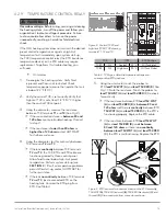
2.5.3  MOTOR ROTATION CHECK

NOTICE

Pump rotation (three-phase only): 

For three-phase 

applications, check for proper pump rotation prior to 
introducing fluid to the pump. Reverse rotation while 
the pump is filled with fluid will cause pump seal failure.

Pump damage:

 Do not run the motor/pump assembly 

dry for more than a few seconds. Running a motor/
pump for a prolonged period without being completely 
filled with fluid may cause damage to the pump seal.

The following procedures are for three-phase 

applications only. Single-phase systems are prewired to 

ensure the pump motor rotates in the correct direction. 

1. 

With main power connected to the heating system 

motor 

(see 

SECOIO  2.5.1

)

, energize the pump 

while observing the rotation of the pump motor fan 

at the rear of the motor. Refer to rotation decal on 

motor for correct rotation.


h

If the pump motor does not rotate in the correct 

direction, disconnect power and switch any two 

electrical leads at the main power terminal block 

(

L1, L2, L3

). Reconnect power. 

Repeat step 1 

to 

ensure motor rotates in the correct direction.

COMPONENTS AND 

OPERATION

The following is an operational description for each of 

the OLA interface and system components.

 OOE:


  Components installed in control box may 

vary depending on the particular system 

configuration purchased.

3.1 

INTERFACE COMPONENTS

3.1.1  LOCAL/OFF/REMOTE SWITCH


local

 – The system is 

on

.


off

 – The system is shut 

off

.


remote

 – The system will turn on and shut 

off on a signal from the 24 V DC remote 

connection. 

See 

SECOIO  2.5.2

.

3.1.2  PRIME BUTTON

Press and hold the 

prime

 button to energize the pump 

motor in order to remove any air in the heating system 

without energizing the elements. 

 OOICE! 

Do not run 

the motor/pump assembly dry for more than five 
seconds at a time.

 OOE:


 The 

prime

 function is intended for use during 

the first run procedure (

see 

SECOIO  3.3.1

) or 

after performing maintenance on the heating 

system or plumbing (

see 

SECOIO  4.2

)

.

3.1.3  RESET BUTTON

Press the 

reset

 button to reset the pump motor protection 

switch without opening the control box. The reset function 

is intended for use immediately following resolving and 
repairing a system fault (

see 

SECOIO  4.1.1)

.

3.1.4  PRESSURE/TEMPERATURE GAUGE

The OLA model features a temperature/pressure gauge 

mounted at the heating tank inlet. The gauge will 

indicate a pressure increase when the pump motor is 

engaged by pressing and holding the 

prime


button or 

during normal operation. The gauge will also indicate the 

fluid’s current temperature.

 OOE:


  Your system’s operating pressure may vary 

depending on the configuration of the engine.

3.1.5  PRESSURE RELIEF VALVE

CAUTION

!

Pressure relief valve

: If the OLA heating system is for 

use with a pressurized fluid system, additional, user-
supplied pressure relief must be installed along the 
heating system outlet plumbing. User-supplied pressure 
relief valve plumbing must be routed back to oil sump 
or to atmospheric pressure. Do not route pressure relief 
plumbing back to heating system tank.

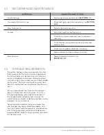
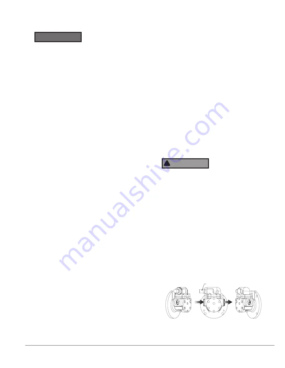
The oil pump pressure relief valve is internal to the pump 

and releases pressure from the discharge side of the 

pump to the suction side of the pump at 75 psi (525 

kPa). No plumbing for this component is required. The 

pressure relief valve cap must always point toward the 

inlet side of the pump. 
The OLA heating system is designed to not exceed 125 

psi (862 kPa); however, the oil pump will not exceed 

75 psi (517 kPa). In the event the pressure relief valve is 

activated, the pump will continue to produce flow, but 

will not exceed a pressure of 75 psi (517 kPa).

PRESSURE RELIEF 

VALVE CAP

PUMP INLET

PUMP OUTLET

Figure 6.  Typical OLA pump assembly. Note that the pressure relief 
valve cap must always point toward the inlet side of pump.

Summary of Contents for OLA

Page 1: ...216348 000 rev1 INSTALLATION OPERATION MANUAL MODEL OLA OIL CIRCULATING HEATING SYSTEM FOR HAZARDOUS LOCATIONS ...

Page 2: ......

Page 3: ...r and serial number ready when contacting the warranty department COPYRIGHT Hotstart Manufacturing Inc is the owner of all trademarks and copyrightable material contained herein all rights are reserved no form of reproduction is authorized without prior written consent from Hotstart Manufacturing Inc NOTE Typical heating system identification plate Your identification plate may vary Corporate Manu...

Page 4: ...ble overcurrent limiting device Power disconnection A means to disconnect the heating system from the power supply is required HOTSTART recommends that a power switch or circuit breaker be located near the heating system for safety and ease of use Flameproof joints Flameproof joints are not intended to be repaired in the field Do not attempt to repair any flameproof joints that become damaged Bend...

Page 5: ... Prime Button 9 3 1 3 Reset Button 9 3 1 4 Pressure Temperature Gauge 9 3 1 5 Pressure Relief Valve 9 3 2 SYSTEM COMPONENTS 10 3 2 1 Motor Protection Switch 10 3 2 2 Control TCR Temperature Control Relay 10 3 2 3 High Limit TCR Temperature Control Relay 10 3 3 HEATING SYSTEM START UP 10 3 3 1 First Run Procedure 11 4 MAINTENANCE AND TROUBLESHOOTING 11 4 1 SYSTEM FAULTS 11 4 1 1 Oil Faults 11 4 2 S...

Page 6: ...iv installation operation manual ola heating system this page intentionally left blank ...

Page 7: ...ions are for reference only and are not to scale See part drawings for dimensions and specifications A local off remote switch B prime button C reset button D Heating element E Oil outlet 1 NPT F High limit resistance temperature device RTD G Heating tank H Identification plate I Control resistance temperature device RTD J Pressure Temperature gauge K Pump motor L Oil pump M Oil inlet 0 5 1 0 1 5 ...

Page 8: ... line The oil pump will continuously circulate fluid throughout the engine or compressor To maintain consistent fluid temperature the heating element will cycle on and off at the user selected temperature control point An oil check valve user supplied and installed near the oil suction port prevents backflow while the engine or compressor is operating When the engine or compressor is shut down the...

Page 9: ...ure it is completely full of fluid while in operation Pump priming Fill supply line with fluid Pump is not self priming Fluid must be present in the pump before start up Trapped air inside the pump will cause pump and seal damage Pump seal damage Do not reduce the oil supply line to an inner diameter smaller than the pump inlet pump seal damage could occur Check valve HOTSTART recommends installin...

Page 10: ...eters To minimize flow restriction HOTSTART recommends using sweeping bends or 45 fittings At a minimum size the oil supply line per the pump inlet NOTICE Do not reduce the supply line inner diameter pump seal damage will occur NOTE To maximize flow and allow the longest possible supply line install the largest practical inner diameter hose for most installations HOTSTART recommends using a hose w...

Page 11: ...CTION PORT SECTION 2 1 1 CHECK VALVE SECTION 2 1 1 ISOLATION VALVE ISOLATION VALVE OIL SUPPLY SECTION 2 1 1 OIL RETURN SECTION 2 1 2 E 2 E 1 V 2 V 3 V 1 COMPONENT DESCRIPTION V 1 USER SUPPLIED CHECK VALVE V 2 USER SUPPLIED FULL FLOW ISOLATION VALVE E 1 OIL PUMP E 2 OIL HEATING ELEMENT V 3 USER SUPPLIED FULL FLOW ISOLATION VALVE ...

Page 12: ... SECTION 2 1 1 ISOLATION VALVE OIL SUPPLY SECTION 2 1 1 OIL RETURN SECTION 2 1 2 ISOLATION VALVE CHECK VALVE SECTION 2 1 1 E 2 E 1 V 2 V 3 V 1 V 4 COMPONENT DESCRIPTION V 1 USER SUPPLIED CHECK VALVE V 2 USER SUPPLIED FULL FLOW ISOLATION VALVE E 1 OIL PUMP E 2 OIL HEATING ELEMENT V 3 USER SUPPLIED FULL FLOW ISOLATION VALVE V 4 OPTIONAL USER SUPPLIED PRV ...

Page 13: ...n Electrical hazard The heating system must be connected to a suitable protective earthing conductor The heating system s power supply must be connected to a suitable overcurrent limiting device A means of disconnection from power supply is required HOTSTART recommends that a power switch or circuit breaker be located near the heating system for safety and ease of use Reference markings on heating...

Page 14: ...utdown connection is wired NC normally closed from the factory see system wiring schematic for directions to switch to NO normally open operation TB2 3 TB2 4 Fault Signal D The fault signal will indicate a heating system shutdown triggered by either the high limit temperature control relay or the motor protection switch see SECTION 4 1 1 TB2 5 TB2 6 Motor Run Signal E A motor run signal indicates ...

Page 15: ...e than five seconds at a time NOTE The prime function is intended for use during the first run procedure see SECTION 3 3 1 or after performing maintenance on the heating system or plumbing see SECTION 4 2 3 1 3 RESET BUTTON Press the reset button to reset the pump motor protection switch without opening the control box The reset function is intended for use immediately following resolving and repa...

Page 16: ...erheating The high limit TCR uses a resistance temperature device RTD located near the tank outlet The default setting for the high limit TCR is 194 F 90 C and should always be at least 18 F 10 C higher than the control TCR set point The high limit TCR hysteresis is not used in the high limit control See Fig 7 Figure 7 OLA motor protection switch left showing stop off A and reset on B buttons To r...

Page 17: ...n the control dial on the temperature control relay TCR1 to the desired temperature setting for engine oil HOTSTART recommends a control temperature on TCR1 of 104 F 40 C The high limit temperature setting on TCR2 should be set at 194 F 90 C See SECTION 3 2 2 and SECTION 3 2 3 7 Turn the local off remote switch to remote to verify the 24 V DC remote signal connection if installed 4 MAINTENANCE AND...

Page 18: ...d contactor coil The contacts on the magnetic contactor should be inspected periodically for welding arc erosion and mechanical wear If any of these conditions exist replace the magnetic contactor HOTSTART recommends contactors be replaced every five years 4 2 5 PUMP SEAL If seal becomes worn replacement pump seals are available To ensure pump seal longevity ensure the supply lines do not restrict...

Page 19: ... below high limit preset temperature Perform system start up see SECTION 4 If fault or temperature problems persist after start up contact HOTSTART for further assistance h h If there is no continuity between TCR terminals T2 and T3 locate connected RTD on the heating tank Unscrew the RTD plug from RTD See Table 3 5 Using the ohmmeter touch the probes to RTD lead TS2 WHT A and lead TS2 RED B See F...

Page 20: ...en to ensure that the heating system is operational for start up Steps must be taken to ensure that water ingress is mitigated at all locations All plugs and caps must remain tight and a suitable cover must be provided for the system The cover must shield the system from direct rain and protect from any directed spray that may occur For any storage longer than three months desiccant bags must be p...

Page 21: ... tripped Check and reset switch If problem occurs again check motor Restart system RTD failure Check TCR and RTD See SECTION 4 2 9 RTD cable failure Check TCR and RTD See SECTION 4 2 9 Oil temperature too low Motor failure Check motor Replace if necessary Heater has been turned off and fluid is cold Allow time for the heating system to heat fluid Heating element failed Check elements for continuit...

Reviews: