3
MECHANICAL INSTALLATION
Control unit
•
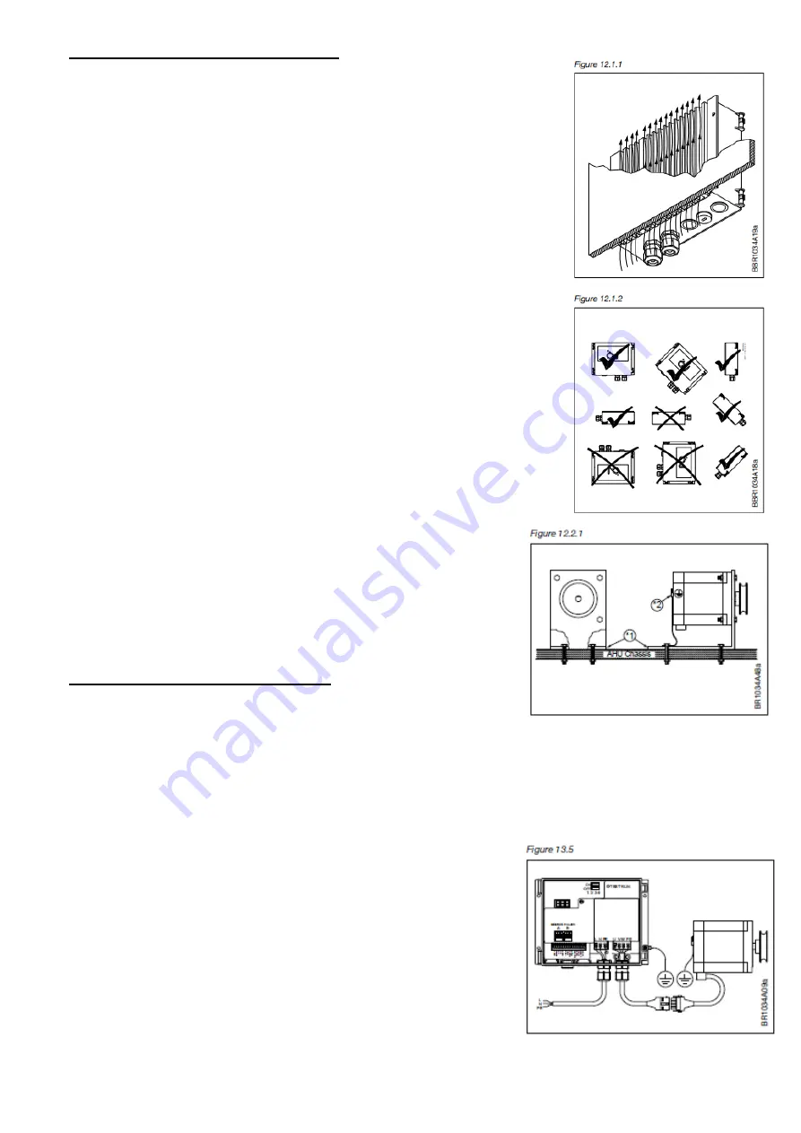
To achieve correct cooling of the DRHX, it must always be positioned
so that there is free airflow around the cooling fins of the DRHX
(see fig. 12.1.1).
•
To achieve the specified enclosure rating, the cable glands must not
point upwards (see fig. 12.1.2).
•
To prevent water from entering the DRHX via cables and cable glands,
ensure that connection is performed in such a way that water is
prevented from accumulating around the cable in the gland.
•
For optimal cooling of the DRHX, it must be installed vertical and on a
slope, with a max. gradient of 45° (see fig. 12.1.1).
The cooling fins on the reverse of the product should thus always be
able to be cooled by the natural thermic up flow past the cooling fins.
•
DRHX must be installed on a flat solid surface.
•
The product should be attached using at least 3 of the screw holes in
the aluminum cooler profile.
•
The control unit should not be installed in direct sunlight.
Motor
•
To ensure integrated rotor guard in the DRHX, and to avoid false
alarms and errors, it is important to install it proper. The stepper motor
comes with four holes for attachment to a solid mounting plate.
•
The mounting plate must be firmly attached to the chassis of the
rotary heat exchanger or AHU (see figure 12.2.1, marked 1)
Do not use vibration dampers or springs!
Must be mounted on a fixed motor bracket.
ELECTRICAL INSTALLATION
Potential equalization
There is a risk of electrical interference if the ground potential between the DRHX and the air handling unit differ
from each other.
It's important to fix the control unit and the motor with metallic screws into the casing
If delivered mounted and fixed inside casing by Hoval above is fulfilled.
If not, following need to be insured of:
•
Lugs should be used, and the equalization conductor should be
attached to the DRHX alu-profile via one of the screws used to
mechanically install the DRHX (see fig.13.5).
•
Recommended cable cross section: 10 mm2.
•
To prevent potential differences between system components, an
equalization conductor must always be fitted.
•
A potential equalization connection must always be installed
between the stepper motor and the chassis of the air handling
unit (see section 12.2).


