7
Digital relay output
•
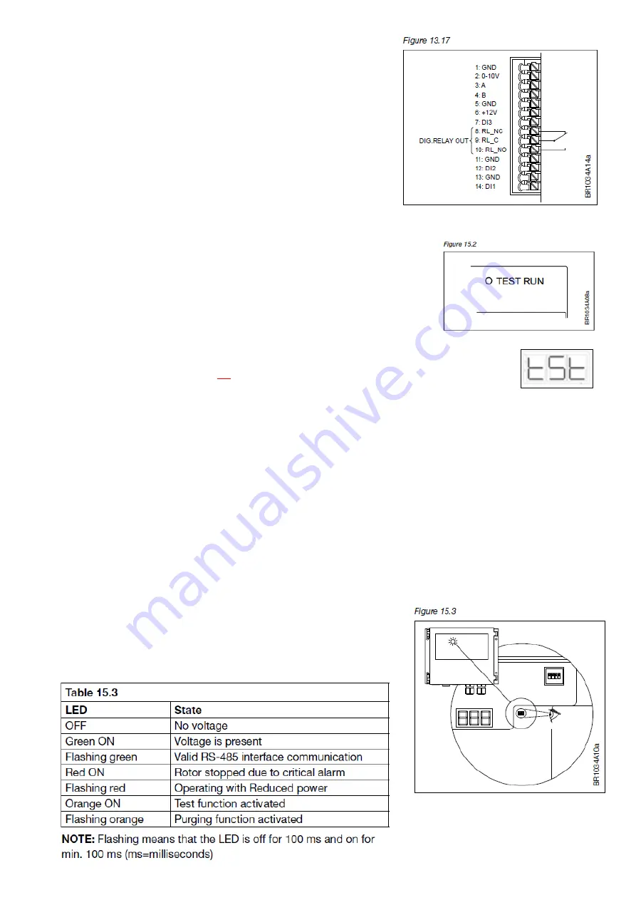
DRHX is equipped with a digital relay output, which can for
example be used for alarm signals (see fig. 13.17).
•
The relay output is a potential-free relay with changeover
switch.
•
The factory-configured function is an alarm relay.
•
Max. load is 2A/30 V DC/24 V AC.
•
Terminals to use:
o
Alarm signal: RL_C (9) and RL_NC (8)
o
Start or Running signal: RL_C (9) and RL_NO (10)
(need to be changed via PC-Tool)
Test functions
DRHX series is provided with a test function in the form of a built-in test push-
button. The test button is located inside the controller in the upper right corner
and must be operated with the controller open (see figure 15.2).
The test button has different functions, depending on how long the button is
pressed in:
•
Running Test for RHE
Belt should be mounted on rotor and pulley.
Start the test by
pressing and continuously holding the test button. The controller will enter test mode.
Visible in display and LED will be orange. The test will remain active until the test button is released.
During this test run the motor will rotate with a maximum speed of 100 rpm.
Stop the test by releasing the test button
. The DRHX will return to normal operation procedure and the
LED will turn green.
•
Pulley calibration test
see page 10
If drive equipment is wired by us from factory
and
mounted in a RHE this test have been done before
delivery.
Instructions on page 10. The pulley calibration test is made without the belt, rotor should not run.
LED indicator
DRHX series is fitted with an LED indicator, see fig. 15.3.
LED can be viewed both with open and closed cover.
For LED indicator codes see table 15.3:


