background image

1

Hoval heating technology

As a full range supplier Hoval helps its customers to select 

innovative system solutions for a wide range of energy sources, 

such as heat pumps, biomass, solar energy, gas, oil and district 

heating. Services range from small commercial to large-scale 

industrial projects.

Responsibility for energy and environment

The Hoval brand is internationally known as one of the leading suppliers of indoor 

climate control solutions. More than 70 years of experience have given us the nec-

essary capabilities and motivation to continuously develop exceptional solutions and 

technically advanced equipment. Maximising energy effi ciency and thus protecting 

the environment are both our commitment and our incentive. Hoval has established 

itself as an expert provider of intelligent heating and ventilation systems that are 

exported to over 50 countries worldwide.

Hoval comfort ventilation

Increased comfort and more effi cient use of energy from 

private housing to business premises: our comfort ventilation 

products provide fresh, clean air for living and working space. 

Our innovative system for a healthy room climate uses heat and 

moisture recovery, while at the same time protecting energy 

resources and providing a healthier environment.

Hoval indoor climate systems

Indoor climate systems ensure top air quality and economical 

usability. Hoval has been installing decentralised systems 

for many years. The key is to use combinations of multiple 

air-conditioning units, even those of different types, that can 

be controlled separately or together as a single system. This 

enables Hoval to respond fl exibly to a wide range of require-

ments for heating, cooling and ventilation.

International

Hoval Aktiengesellschaft

Austrasse 70

9490 Vaduz, Liechtenstein

Tel.  +423 399 24 00

info.klimatechnik@hoval.com

www.hoval.com

United Kingdom

Hoval Ltd.

Northgate, Newark

Nottinghamshire

NG24 1JN

Tel.  01636 672711

heatrecovery@hoval.co.uk

www.hoval.co.uk

TopVent

®

 TV Operating Instructions

Art. No. 4 216 284 / en-01

Summary of Contents for TopVent TV

Page 1: ...TopVent TV Recirculation unit for heating spaces up to 6 m in height Original operating manual Art No 4 216 284 en 01 Page 1 TopVent TV Design installation and operation ...

Page 2: ...ut 7 4 4 Sound data 8 4 5 Dimensions and weights 8 4 6 Specification texts 8 5 Transport and installation 9 5 1 Delivery 9 5 2 Requirements for the installation site 9 5 3 Installation 10 5 4 Hydraulic installation 11 5 5 Electrical installation 12 6 Operation 15 6 1 Initial commissioning 15 6 2 Operation 15 7 Maintenance and repair 16 7 1 Safety 16 7 2 Maintenance 16 7 3 Repair 16 8 Dismantling 1...

Page 3: ...usage over and above this use is considered to be not as intended The manufacturer can accept no liability for damage resulting from improper use 1 2 User group The units are only allowed to be installed operated and maintained by authorised and instructed personnel who are well acquainted with the units and are informed about possible dangers The operating instructions are for operating engineers...

Page 4: ...ore Please read the operating instructions before unpacking installing commis sioning and before maintaining the equipment Store the operating instructions so that they are easily accessible Observe any attached information and warning signs Immediately replace damaged or removed informational and warning signs Follow the local safety and accident prevention regulations at all times Disconnect the...

Page 5: ...n The TopVent TV consists of the following components Heat exchanger consisting of copper tubes and aluminium fins Axial fan with energy saving EC motor and flow optimised fan blades infinitely variable maintenance free and quiet with a high degree of efficiency Compact casing in modern industrial design consisting of high quality ABS robust and easy to clean Suspension set for installing the unit...

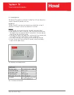
Page 6: ... switch off again Controlling the TopVent units using a door contact switch The connected units are switched on via door contact if the door is open digital input Controlling the fan speed The required speed can be infinitely controlled Pump or valve control The EasyTronic EC provides a signal for switching a pump or a valve digital output Fig 2 EasyTronic EC room temperature controller Technical ...

Page 7: ...A 0 51 1 30 1 70 Supply voltage VAC 230 230 230 Frequency Hz 50 50 50 Max mounting height m 5 5 5 5 5 5 Max horizontal reach m 14 0 22 0 25 0 Table 3 Technical data 4 3 Heat output Temperature of the heating medium 80 60 C 60 40 C Type troom Q tS pW mW Q tS pW mW C kW C kPa l h kW C kPa l h TV 2 15 13 9 34 8 6 7 610 8 3 26 6 3 2 360 20 12 6 37 9 5 6 560 6 8 29 7 2 3 300 TV 4 15 33 5 35 6 11 5 1480...

Page 8: ...s 4 6 Specification texts TopVent TV Recirculation unit for heating spaces up to 6 m in height Sturdy casing made of ABS with pigment additive for UV protection front in RAL 9016 Traffic white and back in RAL 7037 Dusty grey heat exchanger consisting of copper tubes and aluminium fins axial fan with highly efficient EC motor infinitely variable maintenance free and quiet protection rating IP 44 in...

Page 9: ... wrong deliveries and possible transport damage immediately in writing 5 2 Requirements for the installation site Position the units according to the system layout Comply with the minimum and maximum distances All air inlet and air outlet openings must be freely accessible The supply air jet must be free to spread out unhindered X Y X 0 4 m Y Size TV 2 TV 4 TV 5 Distance X m 3 7 6 12 6 12 Distance...

Page 10: ...t the assembly bush into the top opening Position the retaining bracket over the openings Insert M10 screws into the bushes Turn the retaining bracket to the desired position in relation to the unit Tighten the screws to secure the position Place the plugs on the retaining bracket Install both mounting angles with the M8 screws onto the retaining bracket 3 different inclination angles can be used ...

Page 11: ...oved to adjust the air distribution Insulate the hydraulic lines Hydraulically aligned the individual units with one another within the control group to ensure uniform pressure admission Attention Danger of damaging the units Do not fasten any loads to the coil e g by means of the flow or return lines Air vent with shut off Control valve Balancing valve Drain valves Shut off valves Flow Return Fig...

Page 12: ...emperature controller Wire the door contact to the EasyTronic EC or to the desired TopVent unit Wire the pump valve control to the EasyTronic EC Designation Voltage Cable Power supply for units 1 x 230 VAC NYM 3 x 1 5 mm min Power supply for EasyTronic EC 1 x 230 VAC NYM 2 x 1 5 mm min Fan control 0 10 VDC NYM 2 x 1 0 mm Door contact 24 VDC NYM 2 x 1 0 mm Pump Valve control Volt free max 230 VAC m...

Page 13: ...2x1 mm 1 2 2x1 mm 1 2 N PE L 1 2 1 2 1 2 L N PE 10V GND L N PE 2 1 N PE L N PE L 2x1 5 mm Door contact Pump or valve Terminals by the installer 110 230 VAC by the installer EasyTronic EC TopVent TV further TopVent TV max 10 Fig 9 Wiring diagram TopVent TV with central door contact TopVent TV Transport and installation Art No 4 216 284 en 01 Page 13 ...

Page 14: ... mm 1 2 2x1 mm 1 2 N PE L 3 1 L N PE 10V GND 13 14 L N PE 1 3 2 N PE L N PE L 3 1 3 1 2x1 5 mm Door contact Pump or valve 110 230 VAC by the installer EasyTronic EC TopVent TV further TopVent TV max 10 Terminals by the installer Fig 10 Wiring diagram TopVent TV with decentralised door contact TopVent TV Transport and installation Art No 4 216 284 en 01 Page 14 ...

Page 15: ...mponents installed and wired Are all of the respective trade groups installer electrician etc present at the scheduled time Are the system operating personnel present for training at the scheduled time 6 2 Operation The system runs automatically according to the programmed room temperature and the door contact switch Observe the operating instructions for the control system Ensure free air outlet ...

Page 16: ...n working on electrical systems When working in the unit take precautions against unprotected sharp metal edges Immediately replace damaged or removed informational and warning signs Following maintenance work professionally reassemble all dismantled protec tive devices 7 2 Maintenance Maintenance schedule Activity Interval Cleaning the heat exchanger If required at least once per year before the ...

Page 17: ... danger of fatal injury from directly touching live parts even after the unit is switched off Only open the unit after waiting 5 minutes Drain the heating medium circuit Dismantle all media connections Disconnect the unit from fastenings where applicable Remove the unit 9 Disposal Recycle metal components Recycle plastic parts Dispose of electric and electronic parts via hazardous waste If require...

Page 18: ...Art No 4 216 284 en 01 Page 18 ...

Page 19: ...Art No 4 216 284 en 01 Page 19 ...

Page 20: ...ncreased comfort and more efficient use of energy from private housing to business premises our comfort ventilation products provide fresh clean air for living and working space Our innovative system for a healthy room climate uses heat and moisture recovery while at the same time protecting energy resources and providing a healthier environment Hoval indoor climate systems Indoor climate systems ...

Reviews: