- 10 -
Fig. 9
Fig. 10
(2) The top jaws engage with the serration on the master jaws, and the arrangement is secured with
the jaw nuts and bolts.
This construction is adjustable only within a certain range for the top jaws and master jaws.
Adjust the top jaw position between the minimum and the maximum dimensions indicated by "O"
in the table of dimensions (see 6.2).
(3) After determining the installing position, secure the top jaws to the master jaws using the jaw nut
and bolt. Use the fastening torque for the bolts as indicated in Table 8.
Table 8
Bolt size
M10
M12
M16
Tightening torque (N-m)
57.9
101
161
(4) Two bolts are used for one top jaw. As long as the installation bolts
provided for the standard soft jaws or standard hardened jaws are
used, the screw depth of the bolts in relation to the jaw nuts is no
problem, since the value is neither too much nor too little. Should
there be other bolt/nut combinations, however, be sure to keep the
screw depth so that the tip of the bolts will be within 2 mm from the
lower surface of the nuts, or at least not projecting out from below the
nuts' lower surface.
3.3 Forming Top Jaws
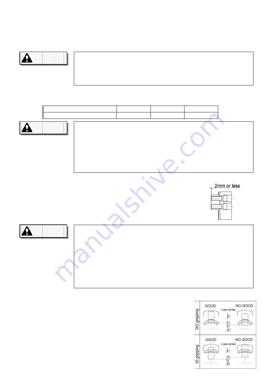
When the top jaws are installed, they must be machine-formed to align
flush with the work piece. When the work piece is gripped, the jaw
stroke should be such that there is one-fourth of the jaw stroke
remaining, as measured from the stroke end. Thus, if you are gripping
the outside diameter (OD) of the work piece with the jaws, one-fourth of
the inside stroke should remain, while you are gripping the inside
diameter (ID) with the jaws, the remaining portion of the stroke should
be on the outside. Grip the work pieces within 2 lines inside of full stroke
mark indicated on No. 1 master jaw and the body (refer to Fig.7).
The cylinder pressure when the top jaws are formed should be the
same as when the work piece is actually being cut.
See Fig. 11 for the specific steps for forming the top jaws.
Use two bolts to secure one top jaw. Be sure to chouse the bolts with
appropriate length.
Use two bolts to secure one top jaw. If only one bolt is used, the top jaw
and/or the bolt may break. If the bolts used to secure the top jaws are
screwed in too shallow into the jaw nuts, the jaw nuts could break. Or, if the
bolts protrude from beneath the lower surface of the jaw nuts, the top jaws
are not secured no matter how far in the bolts are screwed. In either case,
if the screw depth is improper, the jaws and/or work piece may fly off from
the chuck and, in turn, may cause severe personal injury or death to the
operator or bystanders
.
WARNING
WARNING
WARNING
Do not use top jaw out of the adjustable range.
If the top jaws are installed in the radial direction outside of the adjustable
range, the master jaws or jaw nuts will break, making the top jaws and/or
work piece come off in some instances. This may, in turn, cause severe
personal injury or death to the operator or bystanders.
Use exact torque for the installing bolts.
If less torque is used than specified in Table 8 above, the bolts may loosen
in the top jaws and/or the work piece could come off. If the torque is greater
than that specified the master jaws and/or top jaws will deform and
defective operation will result, leading to breakage and release of the top
jaws and/or work piece. In either case, the resulting flying off of work piece
and/or top jaws may lead to severe personal injury or death to the operator
and/or bystanders.
Summary of Contents for H3KB
Page 4: ...2 M5 M M8 M10 M12 M16 M20 N m 7 1 12 1 29 4 57 9 101 161 251...
Page 5: ...3 8 1 4 1 EP...
Page 11: ...9 3 1 3 1 3 1 3 1 3 3 3 3 H 8...
Page 13: ...11 11 D D d d D d 0 75 D D d d D d 0 75 D D d d H7 1 6a d d h6 1 6a...
Page 19: ...17 4 3 4 3 4 3 4 3 ANSI B11 6 1984 section 7 1 9...
Page 21: ...19...
Page 50: ......
Page 51: ......
Page 52: ......


