ISRB
2005 GEA 20260
Page 16 of 24
2500 Series DVJ Blowers
Information in this section not to conflict with other
sections of this manual.
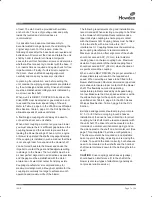
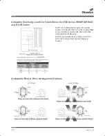
Operating Limitations
Normal DVJ applications have a vacuum on the inlet
and atmospheric pressure on the discharge jet port
connections.
Any unnecessary restrictions of discharge flow or
atmospheric air inlet to the jet port reduces the
cooling air flow and limits blower operation, as the
maximum temperature rise will occur below the
normal limits of vacuum level.
NOTE:
One jet port must have a full size inlet
silencer with no valve or other restrictions. The other
port must have the metal cover plate installed.
Installation
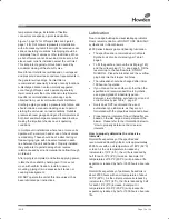
A temporary cover is installed on one jet port and a
permanent cover on the other at the factory. A
silencer must be installed in place of the temporary
cover before operating the blower, however, the
permanent cover and silencer locations may be
exchanged if the installation requires.
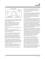
The permanent cover must be removed, both jet
plenums inspected and cleared of foreign material,
then the permanent cover and silencer installed in the
desired locations before operating. Full size jet and
discharge silencers are desirable, however, the jet
silencer may be reduced one nominal size providing
either the vacuum level is less than 18.5” Hg or the
gear speed is below 3650 feet per minute. Both the
jet silencer and the discharge silencer may be
reduced one nominal size in applications with
vacuum levels less than 18.5” Hg and a gear speed
below 3650 feet per minute.
Jet and discharge flow restrictions result in increased
blower temperature rise and should be checked as a
possible cause if the temperature rise limits blower
operation to less than the maximum vacuum level.
Backpressure limits are shown in Table 5 of this
section. No valves should be used in the discharge
piping or jet silencer piping.
Some type of protection, such as a filter or screen
(1/4”mesh) is necessary to stop foreign particle entry
through the jet port. Outside installations may also
require some weather protection to prevent the entry
of rain or snow. An elbow or some other pipe
configuration is desirable to assist in keeping the
screen clear of foreign particles and the direct entry
of rain or snow.
Operation
All check points should be followed with the addition
and/or superseded by the following:
(1, add.) Be careful no rags, bolts, or dirt have been
left in the cylinder slot inlet plenums
(2, add.) No valves should be installed in the
discharge pipe or jet silencer pipe
The blower is suitable for vacuum operation only. A
water manometer should be used on the discharge
plenum to determine that the maximum discharge
pressure has not been exceeded.
Troubleshooting
All troubleshooting points in this manual should be
followed with the addition/or supersedure of the
following:
Excessive temperature rise - check for possible
cylinder slot inlet flow restriction, excessive
backpressure on the discharge, and troubleshooting
checklist in the appropriate instruction and operation
manual.
NOTES:
No valves should be installed in the discharge or jet
silencer pipe.
Jet silencer should be a chamber type (non-packed).
ISRB 2005 GEA 20260.indd 16
17/09/2015 12:53
Summary of Contents for Roots 2500 Series WHISPAIR MAX
Page 14: ...ISRB 2005 GEA 20260 Page 14 of 24 Troubleshooting Checklist...
Page 15: ...ISRB 2005 GEA 20260 Page 15 of 24 2500 Series WHISPAIR Max Blowers...
Page 20: ...ISRB 2005 GEA 20260 Page 20 of 24...
Page 21: ...ISRB 2005 GEA 20260 Page 21 of 24 Assembly of 2500 Series WHISPAIR Max Blower...
Page 22: ...ISRB 2005 GEA 20260 Page 22 of 24 Assembly of 2500 Series DVJ Blower...

