ISRB
2005 GEA 20260
Page 9 of 24
When a unit is BELT DRIVEN, the proper selection of
sheave diameters will result in the required unit
speed. When selecting a sheave to be fitted to the
blower shaft ROOTS recommends a taper lock style
sheave to insure proper contact with the blower shaft.
This flexibility can lead to operating temperature
problems caused by unit speed being too low. Make
sure the drive speed selected is within the allowable
range for the specific unit size, as specified under
Table 2, page 9 in the 2500 Series Whispair Max
Section, Table 3, page 9 in the DVJ Section.
Belt drive arrangements should employ two or more
3V, 5V, or 8V-belts running in grooved sheaves.
Installation of the driver is less critical than for direct
coupling, but its shaft must be level and parallel with
the unit shaft.
The driver should be mounted on
the inlet side of a vertical unit (horizontal piping)
and on the side nearest to the shaft on a
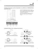
horizontal unit. (See page 7 for acceptable V belt
drive configurations.)
The driver must also be
mounted on an adjustable base to permit installing,
adjusting and removing the V-belts. To position the
driver correctly, both sheaves need to be mounted on
their shafts and the nominal shaft center distance
known for the belt lengths to be used.
CAUTION
: Drive couplings and sheaves (pulleys)
should have an interference fit to the shaft of the
blower (set screw types of attachment generally do
not provide reliable service.)
It is recommended that the drive coupling or sheave
used have a taper lock style bushing which is
properly sized to provide the correct interference fi t
required. Drive couplings, that require heating to fi t
on the blower shaft, should be installed per coupling
manufacturer recommendations. A drive coupling or
sheave should not be forced on to the shaft of the
blower as this could affect internal clearances
resulting in damage to the blower. Engine drive
applications often require special consideration to
drive coupling selection to avoid harmful torsional
vibrations. These vibrations may lead to blower
damage if not dampened adequately. It is often
necessary to install a fl y-wheel and/or a torsionally
soft elastic element coupling based on the Engine
manufacturer recommendations.
When a unit is DIRECT COUPLED to its driver, the
driver RPM must be selected or governed so as not
to exceed the maximum speed rating of the unit.
Refer to Table 1 for allowable speeds of various unit
sizes.
The driver sheave should also be mounted as close
to its bearing as possible, and again should fi t the
shaft correctly. Position the driver on its adjustable
base so that 2/3 of the total movement is available in
the direction away from the unit, and mount the
assembly so that the face of the sheave is accurately
in line with the unit sheave. This position minimizes
belt wear, and allows sufficient adjustment for both
installing and tightening the belts. After belts are
installed, adjust their tension in accordance with the
manufacturer’s instructions. However, only enough
tension should be applied to prevent slippage when
the unit is operating under load. Excessive tightening
can lead to early bearing failures or shaft breakage.
Before operating the drive under power to check
initial belt tension, first remove covers from the unit
connections. Make sure the interior is still clean, and
then rotate the shaft by hand. Place a coarse screen
over the inlet connection to prevent anything being
drawn into the unit while it is operating, and avoid
standing in line with the discharge opening. Put oil in
the sumps per instructions under LUBRICATION.
Piping
Before connecting piping, remove any remaining anti-
rust compound from Unit connections. Clean pipe
should be no smaller than unit connections. In
addition, make sure it is free of scale, cuttings, weld
beads, or foreign material of any kind. To further
guard against damage to the unit, especially when an
inlet filter is not used, install a substantial screen of
16 mesh backed with hardware cloth at or near the
inlet connections. Make provisions to clean this
screen of collected debris after a few hours of
operation. It should be removed when its usefulness
has ended, as the wire will eventually deteriorate and
small pieces going into the unit may cause serious
damage.
Pipe flanges or male threads must meet the unit
connections accurately and squarely. DO NOT
attempt to correct misalignment by springing or
cramping the pipe. In most cases this will distort the
unit casing and cause impeller rubbing. In severe
cases it can prevent operation or result in a broken
drive shaft. For similar reasons, piping should be
supported near the unit to eliminate dead weight
strains. Also, if pipe expansion is likely to occur from
ISRB 2005 GEA 20260.indd 9
17/09/2015 12:53
Summary of Contents for Roots 2500 Series WHISPAIR MAX
Page 14: ...ISRB 2005 GEA 20260 Page 14 of 24 Troubleshooting Checklist...
Page 15: ...ISRB 2005 GEA 20260 Page 15 of 24 2500 Series WHISPAIR Max Blowers...
Page 20: ...ISRB 2005 GEA 20260 Page 20 of 24...
Page 21: ...ISRB 2005 GEA 20260 Page 21 of 24 Assembly of 2500 Series WHISPAIR Max Blower...
Page 22: ...ISRB 2005 GEA 20260 Page 22 of 24 Assembly of 2500 Series DVJ Blower...


