ISRB-2009, Rev. 02_17.
6
Operation
Before operating blower under power for first time, recheck
the unit and the installation thoroughly to reduce the likelihood
of avoidable troubles. Use the following procedure check
list as a guide, but consider any special conditions in the
installation.
• Be certain that no bolts, tools, rags, or debris have been
left in the blower air chamber or piping.
• Recheck blower leveling, drive alignment and tightness
of all mounting bolts if installation is not recent.
• Turn drive shaft by hand to make sure impellers still
rotate without bumping or rubbing at any point.
• Ensure oil levels in main sump are correct.
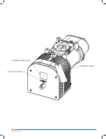
• Bump blower a few revolutions with driver to check that
direction of rotation agree with arrow near blower shaft,
and that both coast freely and come to a stop.
After the preceding points are cleared, blower is ready for trial
operation under “no load” conditions. The following procedure
is suggested to cover this initial operation test period.
• Start blower, let it accelerate to full speed slowly, than
shut off. Slowly engage the power take off and never
pop the clutch on engagement. Listen for knocking
sounds, both power-on and as speed slows down.
• After blower comes to complete stop, repeat above but
let run 2 to 3 minutes. Check for noises, such as
knocking sounds.
• After blower comes to complete stop, operate blower for
about 10 minutes unloaded. Check oil levels. Observe
cylinder and head plate surfaces for development of hot
spots such as burnt paint, including impeller rubs.
Be aware of any noticeable increase in vibration.
Assuming that all trials have been satisfactory, or that
necessary corrections have been made, the blower should
now have final check run of at least one hour under normal
operating conditions. After blower is stated, gradually close
the inlet for vacuum service, or the discharge for pressure
service. At this point it is recommended that pressure gauge
be connected into the discharge line if not already provided,
and that temperature gauge be installed on inlet and
discharge. Readings from these instruments will show
whether pressure or temperature ratings of the blower
are being exceeded.
During the final run, check operating conditions frequently
and observe the oil levels at reasonable intervals. If excessive
noise or local heating develops, shut down immediately and
determine the cause. If either pressure rise or temperature
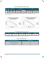
rise across the blower exceeds the limit specified in TABLE
1, shut down and investigate conditions in the piping system.
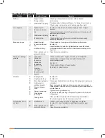
Refer to trouble shooting check list for suggestions on various
problems that may appear.
When the blower vacuum or pressure is at a maximum
intermittent value for over 10 seconds, stop the blower and
remove the line blockage manually. Otherwise the blower
might seize due to excessive operating temperature and
pressure.
Always start blower slowly with power take off and never
pop the clutch on engagement.
Never operate blower above 25 PSI (1.72 bar) pressure rise
on gauge at immediate blower discharge.
Do not operate blower with defective pressure relief valve.
See Table 1, for maximum pressure limits when operating
below maximum speed or above sea level conditions.
See Table 2, for unit internal clearances.
Vibration Assessment Criteria
With measurements taken near the bearing locations on
the housing, see chart below for an appropriate assessment
guide for blower mounted rigidly. In general, blower vibration
levels should be monitored on a regular basis and the
vibration trend observed for progressive or sudden change
in level. As shown on chart below, the level of all pass
vibration will determine need to measure discrete frequency
vibration levels and the action required.
Lubrication
Blower efficiency and life depend on the quality of
maintenance the blower receives. Maintenance must be
done regularly and with care. A clean work space, tools,
solvents, and wiping rags are necessary to avoid transfer
of dirt into the unit. A maintenance chart listing each blower
and scheduling regular checks of the unit is valuable.
Any premium grade, non-detergent industrial grade oil with
rust, oxidation and foam inhibitors will be adequate for
use for most applications. Example: Mobile DTE grade oil.
Because of blower design features, the oil temperature will
remain below 220 °F (104 °C) even at maximum blower
operating temperature rise and ambient temperatures of up
to 120 °F (49 °C). Oil life for mineral base oil is 2000 hours if
operating below 180 °F (82 °C). General rule of thumb: Oil
life at 200 °F (93 °C), would be only 1000 hours and at 220
°F (104 °C) would be only 500 hours. Therefore, if expected
to run at the maximum continuous pressure operation or in
elevated ambient conditions, such as inside enclosure or in
warm environments, consider reduction in oil life and change
with more frequency. When oil temperature does reach
above 180 °F (82 °C), also good synthetic grade oil, such as
Roots synthetic can be used to increase oil life by factor of
3X that of mineral base oils.
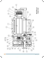
Oil sump is shared for both ends of the blowers and oil fill
can be accomplished by removing breather (item 60) on
drive end cover and filling to the center of sight glass (item
59) on the side of the reservoir on drive end of blower. Oil
sump capacity is approximately 96 fluid ounces (2.85 liters).
Grade of oil to use is based on blower discharge
temperature. See TABLE 3 for recommended oil grades.
NOTE:
Blower discharge temperature of 250 °F, can typically
be achieved ≥ 15 PSI (1000 mbar) pressure rise.
However, can be reached sooner if operating blower
at any of following conditions:
a. higher altitude operation,
b. high ambient temperature,
c. excessive vacuum (inlet filter pressure drop high),
d. lower blower operating speeds.
For operation at temperatures below 10 °F (-12 °C), the
use of heat tracing and synthetic lubricants is recommend.
The pour point should be at least 5 to 10 °F (3 to 5 °C)
below the minimum expected ambient temperature.
For adequate lubrication to the blower internal components,
maximum allowable tilt and roll of the truck is 7.5 degrees
for each direction or in combination.
Summary of Contents for Roots 412 HPT
Page 1: ...www howden com Roots 412 HPT Blower Installation Operation Maintenance Manual...
Page 11: ...11 ISRB 2009 Rev 02_17...
Page 12: ...ISRB 2009 Rev 02_17 12...
Page 13: ...13 ISRB 2009 Rev 02_17...
Page 14: ...ISRB 2009 Rev 02_17 14...
Page 15: ...15 ISRB 2009 Rev 02_17...

