10
GEA30580_Rev_11.15
touch, indicating impeller rubs� Be aware of any
noticeable increase in vibration�
Assuming that all trials have been satisfactory, or that
necessary corrections have been made, the blower
should now have a final check run of at least one
hour under normal operating conditions� After blower
is restarted, gradually close inlet valve to apply
working vacuum gauge or manometer be connected
into the inlet line if not already provided, and that
termometers be in both inlet and discharge lines�
Readings from these instruments will show whether
vacuum or temperature ratings of the blower are
being exceeded�
During the final run, check operating conditions
frequently and observe the oil levels at reasonable
intervals� If excessive noise or local heating develops,
shut down immediately and determine the cause� If
either vacuum or temperature rise across the blower
exceeds the limit specified din this manual, shut
down and investigate conditions in the piping system
or in the process to which air is being supplied�
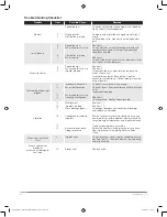
Refer to the TROUBLESHOOTING CHECKLIST� For
suggestions on various problems that may appear�
The blower should now be ready for continuous duty
operation at full load� During the first new days make
periodic checks to determine whether all conditions
remain steady, or at least acceptable� This may be
particularly important if the blower is connected
to a process system where conditions can vary�
At the first opportunity, stop the blower and clean
the temporary inlet and jet port protective screens�
If no appreciable amount of debris has collected,
the screen may be removed� See comments under
INSTALLATION� At this same time, verify leveling,
coupling alignment and mounting bolt tightness�
Vibration Assessment Criteria
With measurements taken at the bearing locations
on the housings, an unfiltered vibration of 1�0 in/sec
peak is considered an appropriate assessment guide
line for rotary lobe blowers rigidly mounted on stiff
foundations�
If the blower is operating above this level then the
installation must be fully evaluated to determine
the source or cause of the vibration, and the cause
corrected�
In general, blower vibration levels should be
monitored on a regular basis and the vibration trend
observed for progressive or sudden change in
level� If such a change occurs, the cause should be
determined through spectral analysis�
Table 3 - Maximum Allowable Operating Conditions
Frame
Inlet Vacuum
Temperature Rise
Max
RPM
Inches
Hg
Mm Hg
°F
°C
827
27
684
275
152
2400
Note: Discharge back pressure must not exceed 10" H
2
O
Table 4 - Blower Internal Clearances
Frame
Size
Impeller Ends
1
Impeller Strip to Cylinder
Impeller Lobes
Max.
Temp.
Rise
°F
Gear End
Opp. G.E.
Inlet
Center
Discharge
Fronts
Backs
827
�036/�040
�006/�008
�020/�023
�014/�016
�020/�023
�021/�025
�011/�015
275
1
Impellers have “wear in” strips� Impeller strip to case clearances as shown
are expected after running the blower, they will not exist at initial blower
assembly� Assembly records need not indicate the strip to case clearance
values�
Maximum clearance listed is for reference only�
GEA30580 Roots 827 DVJ IOM Manual_rev.02.16.indd 10
15/02/2016 12:15:34


