background image

A

A

91

22

44

35

36

90

40

45

72

22

17

19

63

63

8

20

26

23

11

44

SEE NOTE #6

SEE NOTE #5 

SECTION A-A

21

3

12

13

4

1

4

40

46

16

7

90

91

11

26

106

88A

62

62A

74

14

88

14

88

1

5

16

10

10

27

27

27

27

28

28

28

28

54

29

30

30

33

58

59

56

57

48

49

38

38

38

38

34

34

16

16

26

106

19

SEE NOTE #13

SEE NOTE #12

SEE NOTE #10

SEE NOTE #10

SEE NOTE #7

SEE NOTE #7

SEE NOTE  #3

SEE NOTE #4

SEE NOTE #4

A

RELEASED

NOTES:

     1.  DRIVE END COVER TO BE PINNED TO HEADPLATE AFTER           ALIGNING SEAL BORE TO SHAFT WITHIN .001"

     2.  USE LOCTITE 567 ON ALL PIPE THREADS

     3.  APPLY LOCTITE 272 TO SCREW THREADS & TORQUE TO 320 FT-

LBS (44.2KG.M)

     4.  APPLY LOCTITE 272 TO SCREW THREADS & TORQUE TO 23 FT-L

BS (3.2KG.M)

     5.  TORQUE TO 31 FT-LBS (4.3KG.M)

     6.  TORQUE TO 75 FT-LBS (10.4KG.M)

     7.  ITEMS 34 & 54 MUST BE INSTALLED WITH OIL GROOVE AT TOP

.

     8.  REFERENCE RP-91T FOR ASSEMBLY CLEARANCES

     9.  GEAR TO BE INSTALLED WITH ASSEMBLY TOOL TO ACHIEVE MIN

IMUM PUSH-UP

          OF .068".  GEAR FIT MUST BE FREE OF OIL.

    10.  TORQUE NUT TO 500 FT-LBS (69.1KG.M) TORQUE LOCKING SCR

EW TO 16 FT-LBS

            (2.2KG.M)

    11.  PREPARE PISTON RING GROOVES WITH LIGHT COAT OF SLIP PL

ATE FOR INITIAL

           BREAK IN WEAR.

    12.  SLEEVE TO BE HEATED TO 300

F PRIOR TO INSTALLATION ON SHAFT.

    13.  KEY IS TO BE GROUND WITH .001 INTERFERENCE IN SHAFT & 

.000 INTERFERENCE IN HUB


REMOVED #31, OGE COVER PLUG

BMS

6/30/15

16619B

RDA

B

DSIZE

E

D

C

B

A

1

6

7

8

9

10

11

6

7

8

9

10

11

A

C

B

F

E

D

G

F

5

2

3

4

1

2

3

4

5

FINISH IN

µ INCHES

PURCHASE ORDER:  PROJECT:  LOCATION:  EQUIPMENT No. :  CERTIFIED BY:  DATE (M/D/Y): 

CERTIFIED

CAD FORMAT SOLIDWORKS

ORDER

No.

ENGINEER CO: 

SPEC SECTION: 

T2:

ANCHOR BOLT LOCATIONS ±.13 BLOWER INLET & DISCHARGL LOCATIONS ±.25 ALL OTHER DIMENSIONS REFERENCE

T1:

T1

THIRD ANGLE PROJECTION

M/D/Y

MAT'L

. :  

Connersville, IN USA P: 765-827-9200 F: 765-827-9266

SHEET 1 OF 1

5/29/2015

5/29/2015

5/29/2015

4"=1'-0"

JJ

RDA

JJ

827 DVJ - V/H GE DRV

B

SECTIONAL ASSEMBLY

RC-205203023

REV

GEOMETRIC TOLERANCE PER: EP938

REVISIONS

BY

DATE M/D/Y

CHANGE NOTICE

APP

SCALE

DBV.

APP.

CHKD.

DR.

DATE

CONFIDENTIAL AND PROPRIETARY:

DO NOT SCALE FOR DIMENSIONS

ALL DIMENSIONS SHOWN IN BRACKETS [ ] ARE MILLIMETERS

MFG. REF. : 

CAD FILE / DIRECTORY

RC-205203A23 / XASR

PATT. No.

 :  

DIMENSIONAL TOLERANCES PER UNLESS OTHERWISE SPECIFIED

TWO PLACE DECIMALS (.XX)---±.015 THREE PLACE DECIMALS (.XXX)--±.005 FRACTIONAL--±1/64


CHKD

G

THIS DRAWING IS CONFIDENTIAL AND IS THE PROPERTY OF HOWDEN ROOT

S, LLC. THE DRAWING OR ANY PART THEREOF MUST NOT BE COPIED OR O

THERWISE REPRODUCED OR DIVULGED TO ANY OTHER PARTY, OR USED FOR

 MANUFACTURE OR OTHER PURPOSE WITHOUT THE EXPRESS PERMISSION OF

 THE COMPANY.


11

GEA30580_Rev_11.15

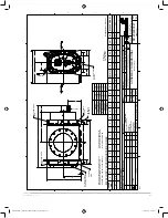
Figur

e 2 - Sectional Assembly

GEA30580 Roots 827 DVJ IOM Manual_rev.02.16.indd   11

15/02/2016   12:15:35

Summary of Contents for Roots 827 DVJ

Page 1: ...www howden com RootsTM 827 DVJ gear end drive blower Installation Operation Maintenance Manual GEA30580 Roots 827 DVJ IOM Manual_rev 02 16 indd 1 15 02 2016 12 15 33...

Page 2: ...ate and piping carefully done Use recommended accessories for operating protection Make sure both driving and driven equipment is correctly lubricated before start up See LUBRICATION Read starting che...

Page 3: ...ach into any opening in the blower while it is operating or while subject to accidental starting Cover external moving parts with adequate guards Disconnect power per lock out tag out procedure before...

Page 4: ...lowers with internal abradable coating are for use with clean dry air only After coating it is not practical to try to measure clearances involving these surfaces before or after running the blower Af...

Page 5: ...rection of cable pull on these bolts as nearly vertical as possible When blower is furnished mounted on a baseplate with or without a driver use of lifting slings passing under the base flange is requ...

Page 6: ...ide strains and end thrust on either shaft are avoided or minimized This will require considerable care in the mounting of the driver The two shafts must be in as near perfect alignment in all directi...

Page 7: ...or cramping the pipe In most cases this will distort the blower casing and cause impeller rubbing In severe cases it can prevent operation or result in a broken drive shaft For similar reasons piping...

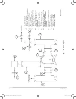
Page 8: ...8 GEA30580_Rev_11 15 Figure 1 Schematic Diagram GEA30580 Roots 827 DVJ IOM Manual_rev 02 16 indd 8 15 02 2016 12 15 34...

Page 9: ...pectancy of petroleum based oils is about 2000 hours with an oil temperature of about 200 F Operation Before operating a blower under power for the first time recheck the unit and the installation tho...

Page 10: ...clean the temporary inlet and jet port protective screens If no appreciable amount of debris has collected the screen may be removed See comments under INSTALLATION At this same time verify leveling...

Page 11: ...SHAFT 000 INTERFERENCE IN HUB REMOVED 31 OGE COVER PLUG BMS 6 30 15 16619B RDA B DSIZE E D C B A 1 6 7 8 9 10 11 6 7 8 9 10 11 A C B F E D G F 5 2 3 4 1 2 3 4 5 FINISH IN INCHES PURCHASE ORDER PROJEC...

Page 12: ...nboard 28 4 Piston ring seal 29 2 Wavy washer spring 30 2 Lock nut bearing 33 1 Oil seal drive shaft 34 2 Brg clamp plate OGE 35 2 Foot R H 36 2 Foot L H 38 4 Sleeve Inboard 40 2 Sight plug 44 18 Hex...

Page 13: ...RANCES PER UNLESS OTHERWISE SPECIFIED BSIZE PATT No CAD FILE DIRECTORY RC 204269A21 XXAD MFG REF 73962021 ALL DIMENSIONS SHOWN IN BRACKETS ARE MILLIMETERS DO NOT SCALE FOR DIMENSIONS 1 2 3 4 5 6 D C B...

Page 14: ...or gears 11 12 13 14 Inadequate lubrication Excessive lubrication Excessive pressure rise Coupling misalignment Check oil sump levels in end covers Check oil levels If correct drain and refill with c...

Page 15: ...15 GEA30580_Rev_11 15 GEA30580 Roots 827 DVJ IOM Manual_rev 02 16 indd 15 15 02 2016 12 15 36...

Page 16: ...our world has revolved around our customers This dedication means our air and gas handling equipment adds maximum value to your operations We have innovation in our hearts and every day we focus on pr...

Reviews: