6
GEA30580_Rev_11.15
With the mounting plate in place and leveled set the
blower on it without bolting and check for rocking� If
it is not solid, determine the total thickness of shims
required under one foot to stop the rocking� Place half
of this under each of the diagonally opposite short
feet, and tighten the mounting studs or screws� Rotate
the drive shaft to make sure the impellers still turn
freely� If the blower is to be direct coupled to a driving
motor, consider the height of the motor shaft and the
necessity for it to be aligned very accurately with the
blower shaft� The best arrangement is for the blower
to be bolted directly to the mounting plate while the
driver is on shims of at least 1/8-inch (3 mm) thickness�
This allows adjustment of motor position in final shaft
alignment by varying the shim thickness�
When the blower and driver have been factory
mounted on a common baseplate, the assembly will
have been properly aligned and is to be treated as a
unit for leveling purposes� Satisfactory installation can
be obtained by setting the baseplate on a concrete
slab that is rigid and free of vibration, and leveling the
tops of the base carefully in two directions so that it is
free of twist� The slab must be provided with suitable
anchor bolts� The use of grouting under and partly
inside the base after it has been carefully leveled by
shimming, is recommended�
It is possible for a base-mounted assembly to
become twisted during shipment
, thus disturbing
the original alignment� For this reason,
make the
following checks after the base has been leveled
and bolted down
� Disconnect the drive and rotate the
blower shaft by hand� It should turn freely at all points�
Loosen the blower foot hold-down screws and deter-
mine whether all feet are evenly in contact with base� If
not, insert shims as required and again check for free
impeller rotation� Finally, if blower is direct coupled to
the driver, check shaft and coupling alignment carefully
and make any necessary corrections�
When the unit is to be directly coupled to its driver, the
driver RPM must be selected or governed so as not
to exceed the maximum speed rating of the blower�
Refer to LIMITATIONS for allowable speeds for various
blower sizes� A flexible type coupling should always
be used to connect the driver and blower shafts� The
standard unit IS NOT DESIGNED for use for V-Belt
Drive�
Coupling halves must be accurately aligned, and a
sufficient gap between shaft ends provided so that
side strains and end thrust on either shaft are avoided
or minimized This will require considerable care in the
mounting of the driver� The two shafts must be in as
near perfect alignment in all directions as possible, and
the gap must be established with the motor armature
on its electrical center if endplay exists�
The following requirements of a good installation are
recommended� Coupling halves must be fitted to the
two shafts with a line to line through �001 inch interfer-
ence fit� Coupling halves must be warmed up, so that
only light tapping is required to install them� Maximum
deviation in offset alignment of the shafts should not
exceed �005 inches (�13 mm) total indicator reading,
taken on the two coupling hubs� Maximum deviation
from parallel of the inside coupling faces should not
exceed �001 inches (�03 mm) when checked at six
points around the coupling�
Operating limitations
To establish and maintain continued satisfac-
tory performance, Roots blower must be operated
within certain approved limiting conditions� The
Manufacturer’s warranty is, of course, contingent on
such operation�
The DVJ cannot be used in pressure applications as
the pressure build-up discharges air outward through
the cylinder slots resulting in high loss in blower
efficiency and reduction in discharge flow�
Any unnecessary restrictions of discharge flow or
atmospheric air inlet to the cylinder slots reduces the
cooling air flow and limits blower operation, as the
maximum temperature rise will occur below the normal
limits of vacuum level�
Note: One cylinder jet port must have a full size inlet
silencer with no valve or other restrictions� The other
port must have the metal cover plate installed�
Jet and discharge flow restrictions result in increased
blower temperature rise and should be checked as
a possible cause if internal metal-to-metal contact
occurs� Back pressure limits on discharge and vacuum
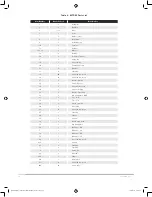
limits on jet are shown in Table 1A� No valves should
be used in the jet or discharge pipe�
Some type of protection, such as a filter or screen
(1/4” mesh) is necessary to stop foreign particle entry
through the jet port� Outside installations may also
require some weather protection to prevent the entry of
rain or snow� An elbow or some other configuration is
desirable to assist in keeping the screen clear of foreign
particles and the direct entry of rain or snow�
All recheck points in this manual should be followed
with the following additions:
1� Be certain no rags, bolts, or dirt have been left in
the cylinder slot inlet plenums�
2� No valves should be installed in the jet or discharge
silencer pipe�
GEA30580 Roots 827 DVJ IOM Manual_rev.02.16.indd 6
15/02/2016 12:15:34


