9
GEA30580_Rev_11.15
Lubrication
A very simple lubrication system is employed in these
blowers� All friction parts—gears, bearings and oil
seals—are lubricated by the action of oil slingers
which dip into the main oil sumps causing oil to
splash directly on gears and bearings� Entrance
of lubricating oil into the blower air chamber is
prevented by the use of double shaft sealing� Lip
type seal, located inboard of the bearings in each
headplate, effectively retain oil within the sumps�
Small leakage that may occur, should the seals wear,
passes into a cavity in each headplate that is vented
and drained downward� In addition, sealing rings are
provided on both shafts where they pass through the
inner walls of the headplates� These serve to reduce
air leakage into the air chamber and also minimize oil
carryover into the air chamber�
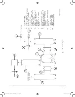
Oil sumps on each end of the blower are filled by
removing top vent plugs,
Item 37
, filling until oil
reaches the middle of the oil level sight gauge,
Item 87
with the
BLOWER NOT OPERATING
, in
order to obtain the correct oil level� Approximate oil
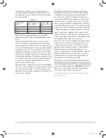
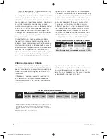
quantities required are listed in Table 1� Use a good
grade of industrial type non-detergent, rust inhibiting,
anti-foaming oil and of correct viscosity per Table 2�
For heavy duty service, a synthetic lubricant, such
as Synfillm GT synthetic oil (Roots p/n 813-106-),
is highly recommended� This synthetic oil has a life
expectancy of 4 times that of petroleum based oils�
The level should never be allowed to fall below the
level gauge when the blower is operating� Oil level
may rise on the gauge during operation, to an extent
depending somewhat on oil temperature and blower
speed, but it should not be permitted to rise above
the top of the oil level gauge�
During the first week of operation, check the oil
levels in the oil sumps about once a day, and watch
for leaks� Replenish as necessary� Thereafter, an
occasional check should be sufficient� It is recom-
mended that the oil be changed after initial 100 hours
of operation� Frequent oil changing is not required
unless the blower is operated in a very dusty loca-
tion� Normal life expectancy of petroleum based oils
is about 2000 hours with an oil temperature of about
200° F�
Operation
Before operating a blower under power for the first
time, recheck the unit and the installation thoroughly
to reduce the likelihood of avoidable troubles� Use
the following procedure list as a guide, but consider
any other special conditions in the installation�
1�
Be certain
that no bolts, tools, rags or dirt have
been left in the blower air chamber�
2�
Be certain
that inlet piping is free of any debris�
If an outdoor intake without filter is used be sure
the opening is located so it cannot pick up dirt
and is protected by a strong screen or grille� Use
of the temporary protective screen at the blower
as described under INSTALLATION is strongly
recommended�
3�
Recheck
blower leveling, drive alignment and
tightness of all mounting bolts if installation is not
recent�
4�
Turn drive shaft by hand
to make sure impel-
lers still rotate without bumping or rubbing at any
point�
5�
Make sure
oil levels in the main oil sumps are
correct�
6�
Check lubrication
of drive� If it is an electric
motor, be sure that power is available and that
electrical overload devices are installed and
workable�
7�
Bump blower
a few revolutions with driver to
check that direction of rotation agrees with arrow
near blower shaft, and that both units coast
freely to a stop�
After the preceding points are cleared, blower is
ready for trial operation under “no-load” conditions
as set up under Item 7� The following procedure is
suggested to cover this initial operation test period�
(a) Start the blower, let it accelerate to full speed,
then shut off� Listen for knocking sounds, both
with power on and as speed slows down�
(b) Repeat above, but let blower run 2 or 3 minutes�
Check for noises, such as knocking sounds�
(c) Operate blower for about 10 minutes unloaded�
Check oil levels� Feel cylinder and headplate
surfaces for development of spots too hot to
Table 1 - Approximate Oil Sump Capacities
Blower
Frame
Size
Gearbox
Blind End Cover
Quarts
Liters
Quarts
Liters
827V
2�1
1�0
1�0
0�5
827H
4�8
2�3
2�0
1�0
Table 2 - Lubricant Recommended
Ambient Temperature
Viscosity Range
SSU @ 100°F (38°C)
Above 90°F (32°C)
320
32° to 90°F (0 to 32°C)
220
0° to 32°F (-18 to 0°C)
100
Below 0°F (-18°C)
68
GEA30580 Roots 827 DVJ IOM Manual_rev.02.16.indd 9
15/02/2016 12:15:34


