ISRB_2002 GEA 19171 Roots URAI
Page 5 of 32
With the mounting plate in place and levelled, set the
unit on it without bolting and check for rocking. If it is not
solid, determine the total thickness of shims required
under one foot to stop rocking. Place half of this under
each of the diagonally-opposite short feet, and tighten
the mounting studs or screws. Rotate the drive shaft to
make sure the impellers turn freely. If the unit is to be
direct coupled to a driving motor, consider the height of
the motor shaft and the necessity for it to be aligned
very accurately with the unit shaft. Best unit
arrangement is directly bolted to the mounting plate
while the driver is on shims of at least 1/8 inch (3mm)
thickness. This allows adjustment of motor position in
final shaft alignment by varying the shim thickness.
Aligning
When unit and driver are factory mounted on a common
baseplate, the assembly will have been properly aligned
and is to be treated as a unit for levelling purposes.
Satisfactory installation can be obtained by setting the
baseplate on a concrete slab that is rigid and free of
vibration, and levelling the top of the base carefully in
two directions so that it is free of twist. The slab must be
provided with suitable anchor bolts. The use of grouting
under and partly inside the levelled and shimmed base
is recommended.
It is possible for a base-mounted assembly to become
twisted during shipment, thus disturbing the original
alignment. For this reason, make the following checks
after the base has been levelled and bolted down.
Disconnect the drive and rotate the unit shaft by hand. It
should turn freely at all points. Loosen the unit foot hold-
down screws and determine whether all feet are evenly
in contact with the base. If not, insert shims as required
and again check for free impeller rotation. Finally, if unit
is direct coupled to the driver, check shaft and coupling
alignment carefully and make any necessary
corrections.
In planning the installation, and before setting the unit,
consider how piping arrangements are dictated by the
unit design and assembly. Drive shaft rotation must be
established accordingly and is indicated by an arrow
near the shaft.
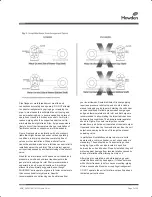
Typical arrangement on vertical units has the drive shaft
at the top with counterclockwise rotation and discharge
to the left. Horizontal units are typically arranged with
the drive shaft at the left with counterclockwise rotation
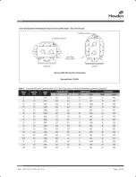
and discharge down. See Figure 4 for other various unit
arrangements and possible conversions.
When a unit is DIRECT COUPLED to its driver, the
driver RPM must be selected or governed so as not to
exceed the maximum speed rating of the unit. Refer to
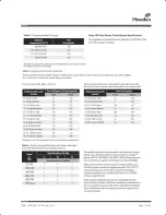
Table 1 for allowable speeds of various unit sizes.
A flexible type coupling should always be used to
connect the driver and unit shafts.
When direct coupling a motor or engine to a blower you
must insure there is sufficient gap between the coupling
halves and the element to prevent thrust loading the
blower bearings. When a motor, engine or blower is
operated the shafts may expand axially. If the coupling
is installed in such a manner that there is not enough
room for expansion the blower shaft can be forced
back into the blower and cause the impeller to contact
the gear end headplate resulting in damage to the
blower. The two shafts must be in as near perfect
alignment in all directions as possible, and the gap must
be established with the motor armature on its electrical
center if end-play exists. Coupling manufacturer’s
recommendations for maximum misalignment, although
acceptable for the coupling, are normally too large to
achieve smooth operation and maximum life of the
blower.
The following requirements of a good installation are
recommended. When selecting a coupling to be fitted to
the blower shaft Howden Roots recommends a taper
lock style coupling to insure proper contact with the
blower shaft. If the coupling must have a straight bore
the coupling halves must be fitted to the two shafts with
a line to line thru .001” interference fit. Coupling halves
must be warmed up per coupling manufacturer’s
recommendations. Maximum deviation in offset
alignment of the shafts should not exceed .005" (.13
mm) total indicator reading, taken on the two coupling
hubs. Maximum deviation from parallel of the inside
coupling faces should not exceed .001" (.03 mm) when
checked at six points around the coupling.
When a unit is BELT DRIVEN, the proper selection of
sheave diameters will result in the required unit speed.
When selecting a sheave to be fitted to the blower shaft
Howden Roots recommends a taper lock style sheave to
insure proper contact with the blower shaft. This
flexibility can lead to operating temperature problems
caused by unit speed being too low. Make sure the drive
speed selected is within the allowable range for the
specific unit size, as specified under Table 1.
Belt drive arrangements usually employ two or more V-
belts running in grooved sheaves. Installation of the
driver is less critical than for direct coupling, but its shaft
must be level and parallel with the unit shaft.
The driver
should be mounted on the inlet side of a vertical unit
(horizontal piping) and on the side nearest to the
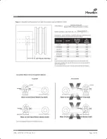
shaft on a horizontal unit. SEE PAGE 6 - Acceptable
ISRB_2002 GEA 19171 Roots URAI.indd 5
17/09/2015 12:52
Summary of Contents for Roots Metric Series
Page 11: ...ISRB_2002 GEA 19171 Roots URAI Page 11 of 32...
Page 13: ...ISRB_2002 GEA 19171 Roots URAI Page 13 of 32...
Page 14: ...ISRB_2002 GEA 19171 Roots URAI Page 14 of 32...
Page 15: ...ISRB_2002 GEA 19171 Roots URAI Page 15 of 32...
Page 16: ...ISRB_2002 GEA 19171 Roots URAI Page 16 of 32...
Page 17: ...ISRB_2002 GEA 19171 Roots URAI Page 17 of 32...
Page 18: ...ISRB_2002 GEA 19171 Roots URAI Page 18 of 32...
Page 19: ...ISRB_2002 GEA 19171 Roots URAI Page 19 of 32...
Page 20: ...ISRB_2002 GEA 19171 Roots URAI Page 20 of 32...
Page 21: ...ISRB_2002 GEA 19171 Roots URAI Page 21 of 32...
Page 22: ...ISRB_2002 GEA 19171 Roots URAI Page 22 of 32...
Page 23: ...ISRB_2002 GEA 19171 Roots URAI Page 23 of 32...
Page 24: ...ISRB_2002 GEA 19171 Roots URAI Page 24 of 32...
Page 25: ...ISRB_2002 GEA 19171 Roots URAI Page 25 of 32...
Page 26: ...ISRB_2002 GEA 19171 Roots URAI Page 26 of 32...
Page 27: ...ISRB_2002 GEA 19171 Roots URAI Page 27 of 32...
Page 28: ...ISRB_2002 GEA 19171 Roots URAI Page 28 of 32...
Page 29: ...ISRB_2002 GEA 19171 Roots URAI Page 29 of 32...
Page 30: ...ISRB_2002 GEA 19171 Roots URAI Page 30 of 32...


