ISRB_2002 GEA 19171 Roots URAI
Page 7 of 32
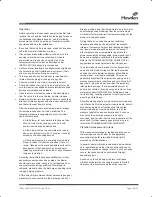
Pipe flanges or male threads must meet the unit
connections accurately and squarely. DO NOT attempt
to correct misalignment by springing or cramping the
pipe. In most cases this will distort the unit casing and
cause impeller rubbing. In severe cases it can prevent
operation or result in a broken drive shaft. For similar
reasons, piping should be supported near the unit to
eliminate dead weight strains. Also, if pipe expansion is
likely to occur from temperature change, installation of
flexible connectors or expansion joints is advisable.
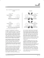
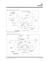
Figure 3 represents an installation with all accessory
items that might be required under various operating
conditions. Inlet piping should be completely free of
valves or other restrictions. When a shut-off valve
cannot be avoided, make sure a full size vacuum relief is
installed nearest the unit inlet. This will protect against
unit overload caused by accidental closing of the shutoff
valve.
Need for an inlet silencer will depend on unit speed and
pressure, as well as sound-level requirements in the
general surroundings. An inlet filter is recommended,
especially in dusty or sandy locations. A discharge
silencer is also normally suggested, even though
WHISPAIR* units operate at generally lower noise levels
than conventional rotary blowers. Specific
recommendations on silencing can be obtained from
your local Howden Roots distributor. Discharge piping
requires a pressure relief valve, and should include a
manual unloading valve to permit starting the unit under
no-load conditions. Reliable pressure/vacuum gauges
and good thermometers at both inlet and discharge are
recommended to allow making the important checks on
unit operating conditions. The back-pressure regulator
shown in Figure 3 is useful mainly when volume
demands vary while the unit operates at constant output.
If demand is constant, but somewhat lower than the unit
output, excess may be blown off through the manual
unloading valve.
In multiple unit installations where two or more units
operate with a common header, use of check valves is
mandatory. These should be of a direct acting or free
swinging type, with one valve located in each line
between the unit and header. Properly installed, they will
protect against damage from reverse rotation caused by
air and material back-flow through an idle unit.
After piping is completed, and before applying power,
rotate the drive shaft by hand again. If it does not move
with uniform freedom, look for uneven mounting, piping
strain, excessive belt tension or coupling misalignment.
DO NOT
operate the unit at this time unless it has been
lubricated per instructions.
ISRB_2002 GEA 19171 Roots URAI.indd 7
17/09/2015 12:52
Summary of Contents for Roots Metric Series
Page 11: ...ISRB_2002 GEA 19171 Roots URAI Page 11 of 32...
Page 13: ...ISRB_2002 GEA 19171 Roots URAI Page 13 of 32...
Page 14: ...ISRB_2002 GEA 19171 Roots URAI Page 14 of 32...
Page 15: ...ISRB_2002 GEA 19171 Roots URAI Page 15 of 32...
Page 16: ...ISRB_2002 GEA 19171 Roots URAI Page 16 of 32...
Page 17: ...ISRB_2002 GEA 19171 Roots URAI Page 17 of 32...
Page 18: ...ISRB_2002 GEA 19171 Roots URAI Page 18 of 32...
Page 19: ...ISRB_2002 GEA 19171 Roots URAI Page 19 of 32...
Page 20: ...ISRB_2002 GEA 19171 Roots URAI Page 20 of 32...
Page 21: ...ISRB_2002 GEA 19171 Roots URAI Page 21 of 32...
Page 22: ...ISRB_2002 GEA 19171 Roots URAI Page 22 of 32...
Page 23: ...ISRB_2002 GEA 19171 Roots URAI Page 23 of 32...
Page 24: ...ISRB_2002 GEA 19171 Roots URAI Page 24 of 32...
Page 25: ...ISRB_2002 GEA 19171 Roots URAI Page 25 of 32...
Page 26: ...ISRB_2002 GEA 19171 Roots URAI Page 26 of 32...
Page 27: ...ISRB_2002 GEA 19171 Roots URAI Page 27 of 32...
Page 28: ...ISRB_2002 GEA 19171 Roots URAI Page 28 of 32...
Page 29: ...ISRB_2002 GEA 19171 Roots URAI Page 29 of 32...
Page 30: ...ISRB_2002 GEA 19171 Roots URAI Page 30 of 32...


