background image

GEA19684  ISRB_2008 rev._11.15

10

Inspection & Maintenance

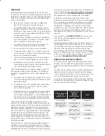
A good program of consistent inspection and maintenance 
is the most reliable method of minimizing repairs to a blower. 
A simple record of services and dates will help keep this 
work on a regular schedule. Basic service needs are:

• 

Lubrication

• 

Checking for hot spots

• 

Checking for increases or changes in vibration and 
noise

• 

Recording of operating pressures and temperatures

Above all, a blower must be operated within its specified 
rating limits, to obtain satisfactory service life.

A newly installed blower should be checked often during 
the first month of full-time operation. Attention there after 
may be less frequent assuming satisfactory performance. 
Lubrication is normally the most important consideration and 
weekly checks of lubricant levels in the gearbox and bear-
ing reservoirs should be customary. Complete oil change 
schedules are discussed under 

LUBRICATION

.

Driver lubrication practices should be in accordance with the 
manufacturer’s instructions. If direct connected to the blower 
through a lubricated type coupling, the coupling should be 
checked and greased each time blower oil is changed. This 
will help reduce wear and prevent unnecessary vibration. In 
a belted drive system, check belt tension periodically and 
inspect for frayed or cracked belts. 

In a new, and properly installed, unit there is no contact 
between the two impellers, or between the impellers and 
cylinder or headplates. Wear is confined to the bearings 
(which support and locate the shafts) the oil seals, and the 
timing gears. All are lubricated and wear should be minimal 
if clean oil of the correct grade is always used. Seals are 
subject to deterioration and wear, and may require replace-
ment at varying periods.

Piston ring seals (28) are designed to operate without rub-
bing contact, once temperature and thermal growth have 
stabilized. The stationary rings will rub the rotating sleeve 
(38) briefly as a result of temperature cycles that occur 
during the startup and shutdown of the unit. The sleeves are 
hardened and the rings are coated with dry lubricant that 
provides for temporary break in wear. Replace piston ring 
seals if they become excessively worn.

Shaft bearings are designed for optimum life under aver-
age conditions with proper lubrication and are critical to the 
service life of the blower. Gradual bearing wear may allow 
a shaft position to change slightly, until rubbing develops 
between impeller and casing. This will cause spot heating, 
which can be detected by observing these surfaces. Sud-
den bearing failure is usually more serious. Since the shaft 
and impeller are no longer supported and properly located, 
extensive general damage to the blower casing and gears is 
likely to occur.

Oil seals should be considered expendable items, to be 
replaced whenever drainage from the headplate vent cavity 
becomes excessive or when the blower is disassembled for 
any reason. Some oil seal leakage may occur since an oil 
film under the lip is required for proper operation. Periodi-
cally leaked oil should be wiped off from surfaces. Minor 
seal weepage should not be considered as indicating seal 
replacement.

Timing gear wear, when correct lubrication is maintained, 
should be negligible. Gear teeth are cut to provide the 
correct amount of backlash, and gears correctly mounted 
on the shafts will accommodate a normal amount of tooth 
wear without permitting contact between lobes of the two 
impellers. However, too high an oil level will cause churning 
and excessive heating. This is indicated by unusually high 
temperature at the bottom of the gear housing. Consequent 
heating of the gears will result in loss of tooth-clearance , 
backlash and rapid wear of the gear teeth usually will de-
velop. Continuation of this tooth wear will eventually produce 
impeller contacts (knocking), and from this point serious 
damage will be unavoidable if blower operation is continued. 
A similar situation can be produced suddenly by gear tooth 
fracture, which is usually brought on by sustained overload-
ing or momentary shock loads.

Problems may also develop from causes other than internal 
parts failure. Operating clearances within a blower are only 
a few thousandths of an inch. This makes it possible for 
impeller interferences or casing rubs to result from shifts in 
the blower mounting, or from changes in piping support. If 
this type of trouble is experienced, and the blower is found 
to be clean, try removing mounting strains. Loosen blower 
mounting bolts and reset the leveling and drive alignment. 
Then tighten mounting again, and make sure that all piping 
meets blower connections accurately and squarely Foreign 
materials sucked into the blower will also cause trouble, 
which can only be cured by disconnecting the piping and 
thoroughly cleaning the blower interior.

A wide range of causes & solutions for operating troubles 
are covered in the 

TROUBLE SHOOTING CHECKLIST

The remedies suggested should be performed by qualified 
mechanics with a good background. Major repairs generally 
are to be considered beyond the scope of maintenance, and 
should be referred to your authorized Roots distributor.

Warranty failures should not be repaired at all, unless spe-
cific approval has been obtained through a Sales Office or 
the factory before starting work. Unauthorized disassembly 
within the warranty period may void the warranty.

GEA19684_ISRB-2008_Tri-RAM_rev02.16.indd   10

15/02/2016   11:17:05

Summary of Contents for Roots Tri-RAM 409

Page 1: ...www howden com RootsTM Tri RAMTM Tri lobe Blowers Installation Operation Maintenance Manual ...

Page 2: ...allation Provide for adequate safeguards against accidents to persons working on or near the equipment during both installation and operation See SAFETY PRECAUTIONS Install all equipment correctly Foundation design must be adequate and piping carefully done Use recommended accessories for operating protection Make sure both driving and driven equipment is correctly lubricated before start up See L...

Page 3: ...sure to arrange connections or taps for instruments such as thermometers and pressure or vacuum gauges at or near the inlet and discharge connec tions of the unit These along with a tachometer will enable periodic checks of operating conditions PRESSURE The pressure rise between inlet and dis charge must not exceed the figure listed for the specific unit frame size concerned Also in any system whe...

Page 4: ...events strain on the extended drive shaft Packaged Units When the unit is furnished mounted on a baseplate with or without a driver use of lifting slings passing under the base flanges is required Arrange these slings so that no strains are placed on the unit casing or mounting feet or on any mounted accessory equipment DO NOT use the lifting lugs in the top of the unit headplates Before starting ...

Page 5: ...ends a taper lock style sheave to insure proper contact with the blower shaft This flexibility can lead to operating temperature problems caused by unit speed being too low Make sure the drive speed selected is within the allowable range for the specific unit size as specified under Table 1 page 13 Belt drive arrangements should employ two or more V belts running in grooved sheaves Installation of...

Page 6: ... valve can not be avoided make sure a full size vacuum relief is installed nearest the unit inlet This will protect against unit overload caused by accidental closing of the shut off valve Need for an inlet silencer will depend on unit speed and pres sure as well as sound level requirements in the general surroundings An inlet filter is recommended especially in dusty or sandy locations A discharg...

Page 7: ...atures contribute to increased lubrication sump temperatures In situations such as blowers in a enclo sure blowers exposed to radiant heat from other sources blowers installed in areas with poor air circulation or ambient temperatures above 80 F the lubrication sump temperature should be measured rather than fully rely on the calculation Bearings and oil seals are lubricated by the action of the t...

Page 8: ...nto the discharge line if not already provided and that thermometers be in both inlet and discharge lines Readings from these instruments will show whether pressure or temperature ratings of the blower are being exceeded During the final run check operating conditions frequently and observe the oil levels at reasonable intervals If exces sive noise or local heating develops shut down immediately a...

Page 9: ...align if questionable Re adjust for correct tension Vibration 17 18 19 20 21 22 23 24 Misalignment Impellers rubbing Worn bearings gears Unbalanced or rub bing impeller Driver or blower loose Piping resonances Scale sludge build ups Casing strain See item 15 See item 10 Check gear backlash and conditions of bearings and replace as indicated Scale or process material may build up on casing and impe...

Page 10: ... more serious Since the shaft and impeller are no longer supported and properly located extensive general damage to the blower casing and gears is likely to occur Oil seals should be considered expendable items to be replaced whenever drainage from the headplate vent cavity becomes excessive or when the blower is disassembled for any reason Some oil seal leakage may occur since an oil film under t...

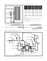
Page 11: ...ual Discharge Unloading Valve Inlet Air Filter Manometers Temporary Screen Expansion Joint AIR BLOWER Expansion Joint with Control Unit Differential Pressure Temperature Switches Discharge Silencer Temperature Gauge Isolation Valve with Limit Switch Check Valve Pressure Relief Valve Back Pressure Regulator optional Vacuum Relief Valve Inlet Silencer Temperature Gauge 11 GEA19684 ISRB_2008 rev _11 ...

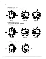
Page 12: ... be unbolted from headplates 1 and discharge relocated as shown Must have authorization for conversion so not to void warranty External sight glasses 37 and breathers 21 must be relocated also Feet 76 and 77 and Lifting Lugs 63 must be relocated as shown DISCH INLET TOP DRV L S DISCH L H DRV BTM DISCH R H DRV TOP DISCH TOP DRV R S DISCH BTM DRV R S DISCH BTM DRV L S DISCH R H DRV BTM DISCH L H DRV...

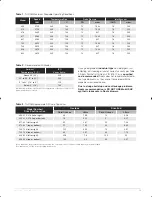
Page 13: ...tic Oil Roots P N 813 106 is specified and recommended Roots does not recommend automo tive type lubricants as they are not formulated with the properties mentioned above Due to sludge build up and seal leakage problems Roots recommendation is DO NOT USE Mobil SHC synthetic lubricants in Roots blowers Ambient temperature is defined as the temperature of the space in which the blower and drive are ...

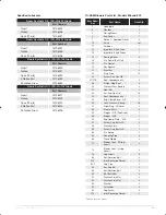
Page 14: ...are 1 21 Breather 2 22 Plug Pipe 12 23 Screw Cap Hex Hd 27 27A Seal Hydrodynamic 4 28 Piston Ring Seal 4 29 Washer Wavy Spring 2 31 Gear Nut 2 32 Scr Cap Hex Hd 16 33 Seal Hydrodynamic 1 34 Brg Clamp Plate D E 2 35 Lock Washer Spring 16 37 Sight Plug Oil Level 2 38 Sleeve Shaft 4 40 Slinger D E Top Drive 1 46 Slinger G E 1 49 Oil Leader L S 1 50 Oil Leader R S 1 54 Brg Clamp Plate G E 2 60 Screw C...

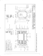
Page 15: ...15 GEA19684 ISRB_2008 rev _11 15 Assembly of Tri RAM Tri Lobe Blowers Models 409 413 416 ...

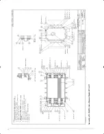
Page 16: ...GEA19684 ISRB_2008 rev _11 15 16 Assembly of Tri RAM Tri Lobe Blowers Models 617 621 ...

Page 17: ...r 1 12 Impeller Shaft Drive 1 13 Impeller Shaft Driven 1 14 Bearing Roller 4 16 Pin Dowel Pull Out 4 17 Pin Dowel 2 19 Key Square 1 21 Breather 2 22 Plug Pipe 12 23 Screw Cap Hex Hd 27 27A Seal Hydrodynamic 4 28 Piston Ring Seal 4 29 Washer Wavy Spring 2 31 Gear Nut 2 32 Scr Cap Hex Hd 16 33 Seal Hydrodynamic 1 34 Brg Clamp Plate D E 2 35 Lock Washer Spring 16 37 Sight Plug Oil Level 2 38 Sleeve S...

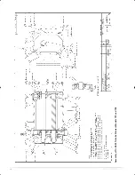
Page 18: ...GEA19684 ISRB_2008 rev _11 15 18 Assembly of Tri RAM Tri Lobe Blowers Models 722 and 728 ...

Page 19: ...r 1 12 Impeller Shaft Drive 1 13 Impeller Shaft Driven 1 14 Bearing Roller 4 16 Pin Dowel Pull Out 4 17 Pin Dowel 2 19 Key Square 1 21 Breather 2 22 Plug Pipe 12 23 Screw Cap Hex Hd 27 27A Seal Hydrodynamic 4 28 Piston Ring Seal 4 29 Washer Wavy Spring 2 31 Gear Nut 2 32 Scr Cap Hex Hd 16 33 Seal Hydrodynamic 1 34 Brg Clamp Plate D E 2 35 Lock Washer Spring 16 37 Sight Plug Oil Level 2 38 Sleeve S...

Page 20: ...GEA19684 ISRB_2008 rev _11 15 20 Assembly of Tri RAM Tri Lobe Blowers Models 826 832 ...

Page 21: ...21 GEA19684 ISRB_2008 rev _11 15 ...

Page 22: ... to improve our products and services and for over 160 years our world has revolved around our customers This dedication means our air and gas handling equipment adds maximum value to your operations We have innovation in our hearts and every day we focus on providing you with the best solutions for your vital operations Howden Roots Howden Roots 900 W Mount St Connersville Indiana USA 47331 Tel 1...

Reviews: