5
GEA19684 ISRB_2008 rev._11.15
It is possible for a base-mounted assembly to become
twisted during shipment, thus disturbing the original align-
ment. For this reason, make the following checks after the
base has been leveled and bolted down. Disconnect the drive
and rotate the unit shaft by hand. It should turn freely at all
points. Loosen the unit foot hold-down screws and determine
whether all feet are evenly in contact with the base. If not,
insert shims as required and again check for free impeller rota-
tion. Finally, if unit is direct coupled to the driver, check shaft
and coupling alignment carefully and make any necessary
corrections.
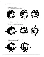
In planning the installation, and before setting the unit,
consider how piping arrangements are dictated by the unit
design and assembly. Drive shaft rotation must be established
accordingly and is indicated by an arrow near the shaft.
Typical arrangement on vertical units has the drive shaft at the
top with counterclockwise rotation and discharge to the left.
Horizontal units are typically arranged with the drive shaft at
the left with counterclockwise rotation and discharge down.
See Figure 4 for other various unit arrangements and possible
conversions.
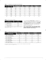
When a unit is DIRECT COUPLED to its driver, the driver
RPM must be selected or governed so as not to exceed the
maximum speed rating of the unit. Refer to Table 1, page 13
for allowable speeds of various unit sizes.
A flexible type coupling should always be used to connect the
driver and unit shafts.
When direct coupling a motor or engine to a blower you must
ensure there is sufficient gap between the coupling halves and
the element to prevent thrust loading the blower bearings.
When a motor, engine or blower is operated the shafts may
expand axially. If the coupling is installed in such a manner
that there is not enough room for expansion the blower shaft
can be forced back into the blower and cause the impeller
to contact the gear end headplate resulting in damage to the
blower. The two shafts must be in as near perfect alignment
in all directions as possible, and the gap must be established
with the motor armature on its electrical center if end-play ex-
ists. Coupling manufacturer’s recommendations for maximum
misalignment, although acceptable for the coupling, are
normally too large to achieve smooth operation and maximum
life of the blower.
The following requirements of a good installation are
recommended. When selecting a coupling to be fitted to the
blower shaft Roots recommends a taper lock style coupling
to ensure proper contact with the blower shaft. Coupling
halves must be fitted to the two shafts with a line to line thru
.001” interference fit. Coupling halves must be warmed up
per coupling manufacturer’s recommendations. Maximum
deviation in offset alignment of the shafts should not exceed
.005” (.13 mm) total indicator reading, taken on the two
coupling hubs. Maximum deviation from parallel of the inside
coupling faces should not exceed .001” (.03 mm) when
checked at six points around the coupling.
When a unit is BELT DRIVEN, the proper selection of sheave
diameters will result in the required unit speed. When selecting
a sheave to be fitted to the blower shaft Roots recommends
a taper lock style sheave to insure proper contact with the
blower shaft. This flexibility can lead to operating temperature
problems caused by unit speed being too low. Make sure
the drive speed selected is within the allowable range for the
specific unit size, as specified under Table 1, page 13.
Belt drive arrangements should employ two or more V-belts
running in grooved sheaves. Installation of the driver is less
critical than for direct coupling, but its shaft must be level and
parallel with the unit shaft.
The driver should be mounted
on the inlet side of a vertical unit (horizontal piping) and
on the side nearest to the shaft on a horizontal unit.
The
driver must also be mounted on an adjustable base to permit
installing, adjusting and removing the V-belts. To position the
driver correctly, both sheaves need to be mounted on their
shafts and the nominal shaft center distance known for the
belt lengths to be used.
CAUTION:
Drive couplings and sheaves (pulleys) should have
an interference fit to the shaft of the blower (set screw types
of attachment generally do not provide reliable service.) It is
recommended that the drive coupling or sheave used have a
taper lock style bushing which is properly sized to provide the
correct interference fit required. Drive couplings, that require
heating to fit on the blower shaft, should be installed per
coupling manufacturer recommendations. A drive coupling or
sheave should not be forced on to the shaft of the blower as
this could affect internal clearances resulting in damage to the
blower.
Engine drive applications often require special con-
sideration to drive coupling selection to avoid harm-
ful torsional vibrations. These vibrations may lead to
blower damage if not dampened adequately. It is often
necessary to install a fly-wheel and/or a torsionally soft
elastic element coupling based on the Engine manufac-
turer recommendations.
The driver sheave should also be mounted as close to its
bearing as possible, and again should fit the shaft correctly.
Position the driver on its adjustable base so that 2/3 of the
total movement is available in the direction away from the unit,
and mount the assembly so that the face of the sheave is
accurately in line with the unit sheave. This position minimizes
belt wear, and allows sufficient adjustment for both installing
and tightening the belts. After belts are installed, adjust their
tension in accordance with the manufacturer’s instructions.
However, only enough tension should be applied to prevent
slippage when the unit is operating under load. Excessive
tightening can lead to early bearing concerns or shaft break-
age.
Before operating the drive under power to check initial belt
tension, first remove covers from the unit connections. Make
sure the interior is still clean, then rotate the shaft by hand.
Place a coarse screen over the inlet connection to prevent
anything being drawn into the unit while it is operating, and
avoid standing in line with the discharge opening. Put oil in the
sumps per instructions under
LUBRICATION
.
Piping
Before connecting piping, remove any remaining anti-rust
compound from Unit connections. Clean pipe should be no
smaller than unit connections. In addition, make sure it is
free of scale, cuttings, weld beads, or foreign material of any
kind. To further guard against damage to the unit, especially
when an inlet filter is not used, install a substantial screen
GEA19684_ISRB-2008_Tri-RAM_rev02.16.indd 5
15/02/2016 11:17:05
Summary of Contents for Roots Tri-RAM 409
Page 1: ...www howden com RootsTM Tri RAMTM Tri lobe Blowers Installation Operation Maintenance Manual ...
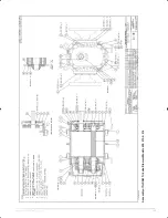
Page 15: ...15 GEA19684 ISRB_2008 rev _11 15 Assembly of Tri RAM Tri Lobe Blowers Models 409 413 416 ...
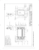
Page 16: ...GEA19684 ISRB_2008 rev _11 15 16 Assembly of Tri RAM Tri Lobe Blowers Models 617 621 ...
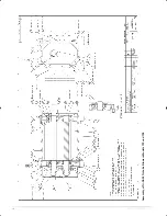
Page 18: ...GEA19684 ISRB_2008 rev _11 15 18 Assembly of Tri RAM Tri Lobe Blowers Models 722 and 728 ...
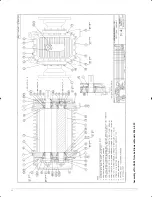
Page 20: ...GEA19684 ISRB_2008 rev _11 15 20 Assembly of Tri RAM Tri Lobe Blowers Models 826 832 ...


