background image

GEA19684  ISRB_2008 rev._11.15

6

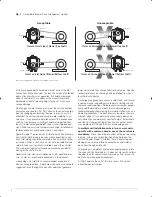
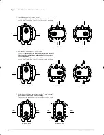
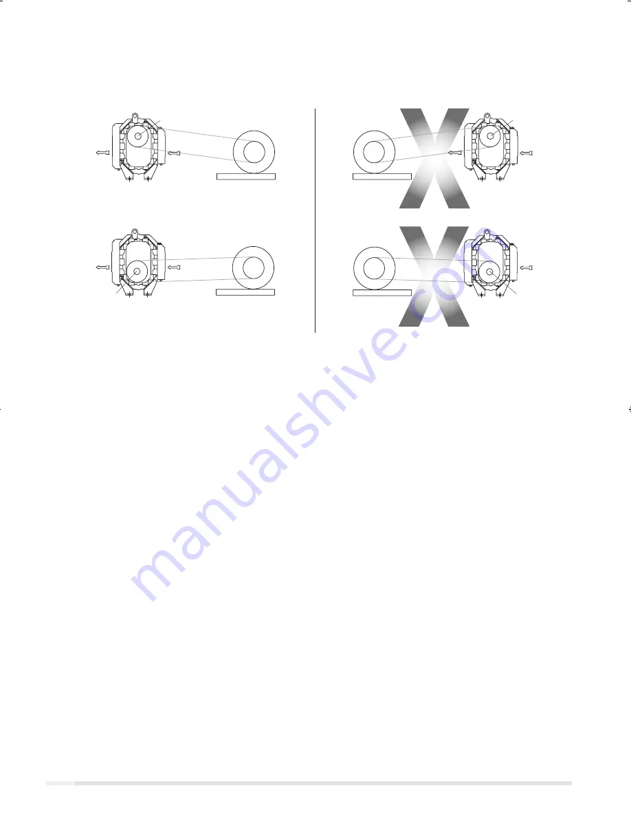
Motor on Inlet Side of Blower (Top Shaft)

Motor on Inlet Side of Blower (Bottom Shaft)

Motor on Drive Shaft

Side of Blower

Motor on Driven Shaft

Side of Blower

Motor on Discharge Side of Blower (Bottom Shaft)

Motor on Discharge Side of Blower (Top Shaft)

Top Shaft

INLET

DISCHARGE

Top Shaft

INLET

DISCHARGE

Bottom Shaft

INLET

DISCHARGE

INLE

T

DISCHAR

GE

Bottom Shaft

Drive Shaft

Driven Shaft

INLE

T

DISCHAR

GE

Drive Shaft

Driven Shaft

INLET

DISCHARGE

Fig. 1

 - Acceptable Blower Drive Arrangement Options

Above are suggested locations for available accessories.

Acceptable

Unacceptable

of 16 mesh backed with hardware cloth at or near the inlet 
connections. Make provisions to clean this screen of collected 
debris after a few hours of operation. It should be removed 
when its usefulness has ended, as the wire will eventually 
deteriorate and small pieces going into the unit may cause 
serious damage.

Pipe flanges or male threads must meet the unit connections 
accurately and squarely. DO NOT attempt to correct misalign-
ment by springing or cramping the pipe. In most cases this 
will distort the unit casing and cause impeller rubbing. In se-
vere cases it can prevent operation or result in a broken drive 
shaft. For similar reasons, piping should be supported near 
the unit to eliminate dead weight strains. Also, if pipe expan-
sion is likely to occur from temperature change, installation of 
flexible connectors or expansion joints is advisable. 

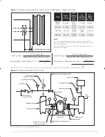
Figure 3, page 11 represents an installation with all accessory 
items that might be required under various operating condi-
tions. Inlet piping should be completely free of valves or other 
restrictions. When a shut-off valve can not be avoided, make 
sure a full size vacuum relief is installed nearest the unit inlet. 
This will protect against unit overload caused by accidental 
closing of the shut-off valve.

Need for an inlet silencer will depend on unit speed and pres-
sure, as well as sound-level requirements in the general 

surroundings. An inlet filter is recommended, especially in 
dusty or sandy locations. A discharge silencer is also normally 
suggested, even though Whispair units operate at generally 

lower noise levels than conventional rotary blowers. Specific 
recommendations on silencing can be obtained from your 
local Roots distributor.

Discharge piping requires a pressure relief valve, and should 
include a manual unloading valve to permit starting the unit 
under no-load conditions. Reliable pressure/vacuum gauges 
and good thermometers at both inlet and discharge are 
recommended to allow making the important checks on unit 
operating conditions. The back-pressure regulator shown in 
Figure 3, page 11 is useful mainly when volume demands 
vary while the unit operates at constant output. If demand is 
constant, but somewhat lower than the unit output, excess 
may be blown off through the manual unloading valve.

In multiple unit installations where two or more units 
operate with a common header, use of check valves is 
mandatory.

 These should be of a direct acting or free swing-

ing type, with one valve located in each line between the 
unit and header. Properly installed, they will protect against 
damage from reverse rotation caused by air and material 
back-flow through an idle unit.

After piping is completed, and before applying power, rotate 
the drive shaft by hand again. If it does not move with uniform 
freedom, look for uneven mounting, piping strain, excessive 
belt tension or coupling misalignment.

DO NOT operate the unit at this time unless it has been 
lubricated per instructions.

GEA19684_ISRB-2008_Tri-RAM_rev02.16.indd   6

15/02/2016   11:17:05

Summary of Contents for Roots Tri-RAM 409

Page 1: ...www howden com RootsTM Tri RAMTM Tri lobe Blowers Installation Operation Maintenance Manual ...

Page 2: ...allation Provide for adequate safeguards against accidents to persons working on or near the equipment during both installation and operation See SAFETY PRECAUTIONS Install all equipment correctly Foundation design must be adequate and piping carefully done Use recommended accessories for operating protection Make sure both driving and driven equipment is correctly lubricated before start up See L...

Page 3: ...sure to arrange connections or taps for instruments such as thermometers and pressure or vacuum gauges at or near the inlet and discharge connec tions of the unit These along with a tachometer will enable periodic checks of operating conditions PRESSURE The pressure rise between inlet and dis charge must not exceed the figure listed for the specific unit frame size concerned Also in any system whe...

Page 4: ...events strain on the extended drive shaft Packaged Units When the unit is furnished mounted on a baseplate with or without a driver use of lifting slings passing under the base flanges is required Arrange these slings so that no strains are placed on the unit casing or mounting feet or on any mounted accessory equipment DO NOT use the lifting lugs in the top of the unit headplates Before starting ...

Page 5: ...ends a taper lock style sheave to insure proper contact with the blower shaft This flexibility can lead to operating temperature problems caused by unit speed being too low Make sure the drive speed selected is within the allowable range for the specific unit size as specified under Table 1 page 13 Belt drive arrangements should employ two or more V belts running in grooved sheaves Installation of...

Page 6: ... valve can not be avoided make sure a full size vacuum relief is installed nearest the unit inlet This will protect against unit overload caused by accidental closing of the shut off valve Need for an inlet silencer will depend on unit speed and pres sure as well as sound level requirements in the general surroundings An inlet filter is recommended especially in dusty or sandy locations A discharg...

Page 7: ...atures contribute to increased lubrication sump temperatures In situations such as blowers in a enclo sure blowers exposed to radiant heat from other sources blowers installed in areas with poor air circulation or ambient temperatures above 80 F the lubrication sump temperature should be measured rather than fully rely on the calculation Bearings and oil seals are lubricated by the action of the t...

Page 8: ...nto the discharge line if not already provided and that thermometers be in both inlet and discharge lines Readings from these instruments will show whether pressure or temperature ratings of the blower are being exceeded During the final run check operating conditions frequently and observe the oil levels at reasonable intervals If exces sive noise or local heating develops shut down immediately a...

Page 9: ...align if questionable Re adjust for correct tension Vibration 17 18 19 20 21 22 23 24 Misalignment Impellers rubbing Worn bearings gears Unbalanced or rub bing impeller Driver or blower loose Piping resonances Scale sludge build ups Casing strain See item 15 See item 10 Check gear backlash and conditions of bearings and replace as indicated Scale or process material may build up on casing and impe...

Page 10: ... more serious Since the shaft and impeller are no longer supported and properly located extensive general damage to the blower casing and gears is likely to occur Oil seals should be considered expendable items to be replaced whenever drainage from the headplate vent cavity becomes excessive or when the blower is disassembled for any reason Some oil seal leakage may occur since an oil film under t...

Page 11: ...ual Discharge Unloading Valve Inlet Air Filter Manometers Temporary Screen Expansion Joint AIR BLOWER Expansion Joint with Control Unit Differential Pressure Temperature Switches Discharge Silencer Temperature Gauge Isolation Valve with Limit Switch Check Valve Pressure Relief Valve Back Pressure Regulator optional Vacuum Relief Valve Inlet Silencer Temperature Gauge 11 GEA19684 ISRB_2008 rev _11 ...

Page 12: ... be unbolted from headplates 1 and discharge relocated as shown Must have authorization for conversion so not to void warranty External sight glasses 37 and breathers 21 must be relocated also Feet 76 and 77 and Lifting Lugs 63 must be relocated as shown DISCH INLET TOP DRV L S DISCH L H DRV BTM DISCH R H DRV TOP DISCH TOP DRV R S DISCH BTM DRV R S DISCH BTM DRV L S DISCH R H DRV BTM DISCH L H DRV...

Page 13: ...tic Oil Roots P N 813 106 is specified and recommended Roots does not recommend automo tive type lubricants as they are not formulated with the properties mentioned above Due to sludge build up and seal leakage problems Roots recommendation is DO NOT USE Mobil SHC synthetic lubricants in Roots blowers Ambient temperature is defined as the temperature of the space in which the blower and drive are ...

Page 14: ...are 1 21 Breather 2 22 Plug Pipe 12 23 Screw Cap Hex Hd 27 27A Seal Hydrodynamic 4 28 Piston Ring Seal 4 29 Washer Wavy Spring 2 31 Gear Nut 2 32 Scr Cap Hex Hd 16 33 Seal Hydrodynamic 1 34 Brg Clamp Plate D E 2 35 Lock Washer Spring 16 37 Sight Plug Oil Level 2 38 Sleeve Shaft 4 40 Slinger D E Top Drive 1 46 Slinger G E 1 49 Oil Leader L S 1 50 Oil Leader R S 1 54 Brg Clamp Plate G E 2 60 Screw C...

Page 15: ...15 GEA19684 ISRB_2008 rev _11 15 Assembly of Tri RAM Tri Lobe Blowers Models 409 413 416 ...

Page 16: ...GEA19684 ISRB_2008 rev _11 15 16 Assembly of Tri RAM Tri Lobe Blowers Models 617 621 ...

Page 17: ...r 1 12 Impeller Shaft Drive 1 13 Impeller Shaft Driven 1 14 Bearing Roller 4 16 Pin Dowel Pull Out 4 17 Pin Dowel 2 19 Key Square 1 21 Breather 2 22 Plug Pipe 12 23 Screw Cap Hex Hd 27 27A Seal Hydrodynamic 4 28 Piston Ring Seal 4 29 Washer Wavy Spring 2 31 Gear Nut 2 32 Scr Cap Hex Hd 16 33 Seal Hydrodynamic 1 34 Brg Clamp Plate D E 2 35 Lock Washer Spring 16 37 Sight Plug Oil Level 2 38 Sleeve S...

Page 18: ...GEA19684 ISRB_2008 rev _11 15 18 Assembly of Tri RAM Tri Lobe Blowers Models 722 and 728 ...

Page 19: ...r 1 12 Impeller Shaft Drive 1 13 Impeller Shaft Driven 1 14 Bearing Roller 4 16 Pin Dowel Pull Out 4 17 Pin Dowel 2 19 Key Square 1 21 Breather 2 22 Plug Pipe 12 23 Screw Cap Hex Hd 27 27A Seal Hydrodynamic 4 28 Piston Ring Seal 4 29 Washer Wavy Spring 2 31 Gear Nut 2 32 Scr Cap Hex Hd 16 33 Seal Hydrodynamic 1 34 Brg Clamp Plate D E 2 35 Lock Washer Spring 16 37 Sight Plug Oil Level 2 38 Sleeve S...

Page 20: ...GEA19684 ISRB_2008 rev _11 15 20 Assembly of Tri RAM Tri Lobe Blowers Models 826 832 ...

Page 21: ...21 GEA19684 ISRB_2008 rev _11 15 ...

Page 22: ... to improve our products and services and for over 160 years our world has revolved around our customers This dedication means our air and gas handling equipment adds maximum value to your operations We have innovation in our hearts and every day we focus on providing you with the best solutions for your vital operations Howden Roots Howden Roots 900 W Mount St Connersville Indiana USA 47331 Tel 1...

Reviews: