Page 1 of 8
Technical Bulletin:
Issue 3 – March 2014
Calibration of the Regulating Unit
on VARIAX
®
B & C Hub Fans
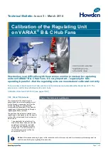
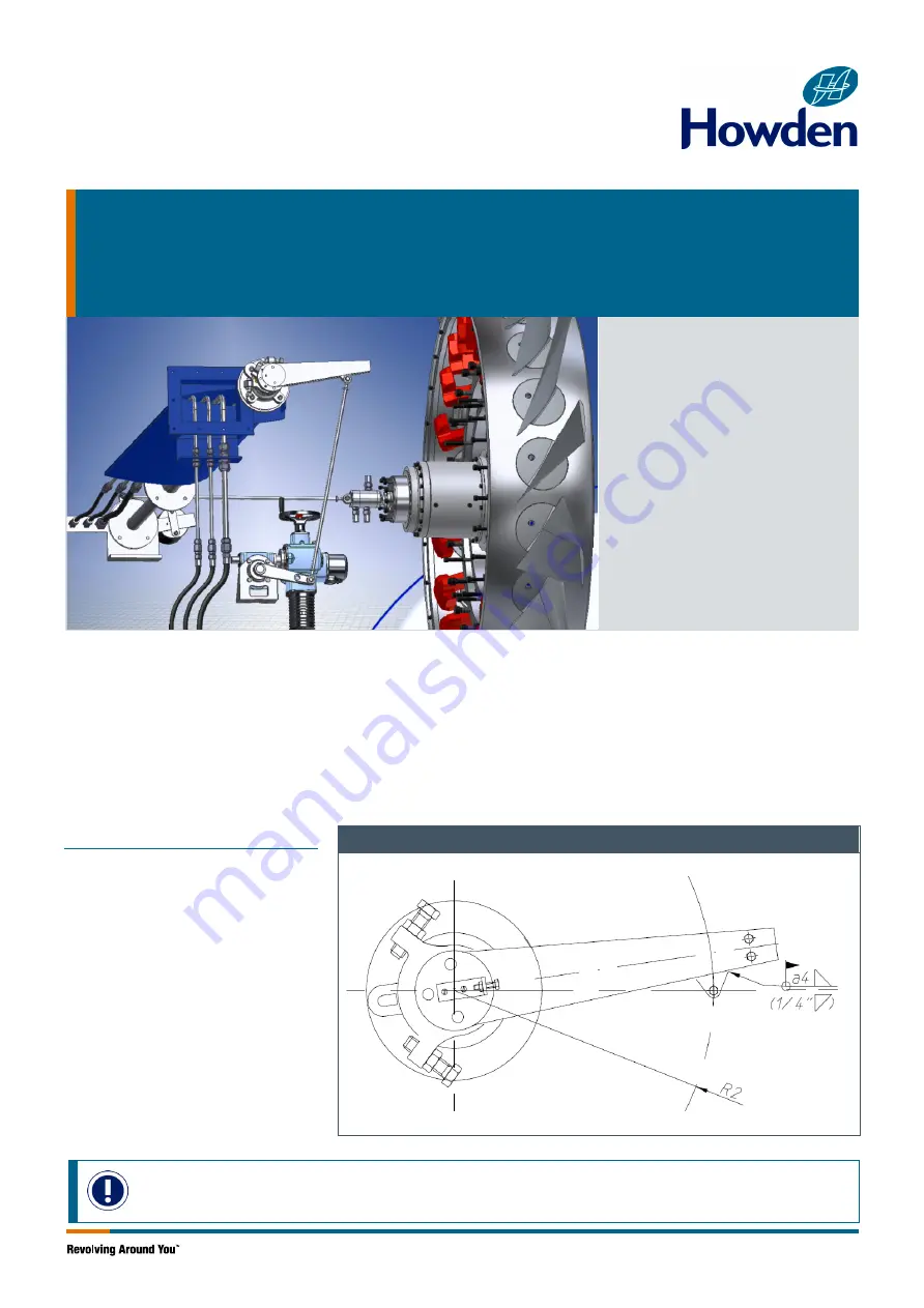
Internal and external
regulating parts –
schematic view
Howden has seen difficulties with the previous erection procedure for regulating
units on VARIAX
®
B & C Hub Fans. It is very important – especially for fans
operating in parallel – that the regulating units are mounted and calibrated correctly.
This procedure is implemented in all new erection and maintenance manuals edited after December 2013. The
procedure is valid for fans with Howden B- and C-hubs.
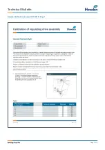
Verification Document V213351-9 (see pages 7/8/9).
3.20 Blade Pitch Actuator
The movement of the actuator lever is
transmitted to the external regulating arm of
the fan through a connecting rod. From the
external regulating arm the regulating
movements are transmitted to the hydraulic
regulating unit (hydraulic cylinder) through a
regulating shaft and a pull fork.
The position of the actuator in relation to the
regulating arm is designed so that the angular
motion of the actuator and the air volume are
almost linear.
1.
The pedestal for the actuator on the
side of the diffuser has been mounted
according to the drawing in chapter
10.00 of the Fan Manuals “Actuator
Arrangement”. Verify the location of
the bracket is correct in verification
document V213351-9.
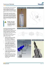
Figure 1: Bracket on outer regulating arm
Notice:
All dimensions and angle given in this instruction are for reference only and the relevant project drawings must be
used when calibrating the regulating drive assembly.

