background image

Technical Bulletin 


Page 2 of 8 


2. 

Verify the regulating arm bracket (see 

Figure 1) on the outer regulating arm  

is at the correct radius according to the 

drawing “Actuator Arrangement “ 

3. 

Check / adjust actuator crank length 

“R1” (Figure 2) according to above 

mentioned drawings. 

4. 

Check measurements “L1” and “L2” 

(Figure 2) according to the above 

mentioned drawings – correct if 

necessary. If tolerances are greater 

than ± 3 mm (0.12”) contact Howden 

for new calculation of “L3”. 

5. 

Mount the rod ends on the external 

regulating arm and adjust the 

connecting rod length “L3 (Figure 2) 

according to above mentioned 

drawings. 

6. 

Adjust the actuator until the bracket on 

external regulating arm is in horizontal 

position – see Figure 2. According to 

above mentioned drawings. 


Checkpoint: 

Check 

measurement of the outer 

regulating arrangement –  

check horizontal position for  

the bracket – see Calibration  

of Regulating Drive Assembly 

in verification document.


For electrical connections please see the 

actual terminal plan in Fan Manuals. 
 

3.21  Calibration of the Regulating 

Drive Assembly (Internal and 

External) 

Adjustment of the regulating drive assembly 

is very important to obtain an approximately 

linear control of the blade pitch. This means 

that the speed of the hydraulic cylinder is 

constant. Regulating Drive geometry is 

designed so that the torque from the actuator 

cannot "break" the external regulating arm 

(activating the torque switch) during normal 

operation. 
The 

theoretical

 minimum and maximum blade 

angles can be found in the fan performance 

curve (blade angles) in chapter 2.00 in Fan 

Manuals. See example copy in Figure 3. 


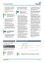
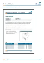
Checkpoint: 

Note actual 

theoretical minimum blade 

angle and actual maximum 

blade angle in document 

V213351-9.


Any blade angle (maximum/minimum) 

references in  section 3;00 of the IOM manual 

must be verified by comparing the blade 

angle on the fan performance curve in 

chapter 2:00 of the IOM manual. Any 

deviations may be reported to Howden for 

clarification. 

Figure 2: Extract from drawing “Actuator Arrangement” 


Figure 3: Fan Curve – find actual curve in Fan Manual “Performance Data” 

Min blade angle = lowest mentioned angle + 1: (here 30+1=31) 

Max blade angle = highest mentioned working point +1: (here 77+1=78) 


Summary of Contents for VARIAX B

Page 1: ...er is transmitted to the external regulating arm of the fan through a connecting rod From the external regulating arm the regulating movements are transmitted to the hydraulic regulating unit hydraulic cylinder through a regulating shaft and a pull fork The position of the actuator in relation to the regulating arm is designed so that the angular motion of the actuator and the air volume are almos...

Page 2: ...uals 3 21 Calibration of the Regulating Drive Assembly Internal and External Adjustment of the regulating drive assembly is very important to obtain an approximately linear control of the blade pitch This means that the speed of the hydraulic cylinder is constant Regulating Drive geometry is designed so that the torque from the actuator cannot break the external regulating arm activating the torqu...

Page 3: ... regulate slow increase the pressure relief valve setting until the hub moves Stop the Hydraulics and observe site safety regulations for working on energized equipment and fan blades 1 Dismount one blade and mount the blade adjustment tool onto the blade pivot in the hub See Figure 6 Note the blade pivot number at the verification document V213351 9 2 Start the control oil unit for supplying oil ...

Page 4: ...anical switches can be adjusted to the position corresponding to the fan stall cancelling angle 17 The internal end of travel limit switches in the actuator should be adjusted according to the supplier s instructions 18 When adjusted the blade angles example in Table 1 should be reached recalculate mA value for stall cancelling for actual blade angles 19 Close the blades carefully to minimum e g 3...

Page 5: ... adjustable counterweight 30 mounted on a lever 29 The counterweight is mounted to balance the spring inside of the hydraulic cylinder which acts on the pilot valve forcing it to go out of position If not balanced hydraulic pressure will result in an uncontrolled movement of the hydraulic piston Adjustment of the counterweight balancing the hydraulic pressure is done from the inside of the inner t...

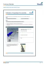
Page 6: ...Technical Bulletin Page 6 of 8 Howden Verification document V213351 9 Page 1 ...

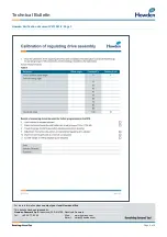
Page 7: ...Technical Bulletin Page 7 of 8 Howden Verification document V213351 9 Page 2 ...

Page 8: ...e contact your local Howden office This bulletin has been released by Howden Denmark ApS Industrivej 23 DK 4700 Næstved Denmark Tel 45 55 77 62 62 Web www howden com Email variax howden com Page 8 of 8 Howden Verification document V213351 9 Page 3 ...

Reviews: