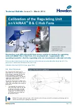
Technical Bulletin
Page 2 of 8
2.
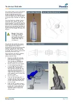
Verify the regulating arm bracket (see
Figure 1) on the outer regulating arm
is at the correct radius according to the
drawing “Actuator Arrangement “
3.
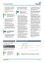
Check / adjust actuator crank length
“R1” (Figure 2) according to above
mentioned drawings.
4.
Check measurements “L1” and “L2”
(Figure 2) according to the above
mentioned drawings – correct if
necessary. If tolerances are greater
than ± 3 mm (0.12”) contact Howden
for new calculation of “L3”.
5.
Mount the rod ends on the external
regulating arm and adjust the
connecting rod length “L3 (Figure 2)
according to above mentioned
drawings.
6.
Adjust the actuator until the bracket on
external regulating arm is in horizontal
position – see Figure 2. According to
above mentioned drawings.
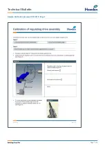
Checkpoint:
Check
measurement of the outer
regulating arrangement –
check horizontal position for
the bracket – see Calibration
of Regulating Drive Assembly
in verification document.
For electrical connections please see the
actual terminal plan in Fan Manuals.
3.21 Calibration of the Regulating
Drive Assembly (Internal and
External)
Adjustment of the regulating drive assembly
is very important to obtain an approximately
linear control of the blade pitch. This means
that the speed of the hydraulic cylinder is
constant. Regulating Drive geometry is
designed so that the torque from the actuator
cannot "break" the external regulating arm
(activating the torque switch) during normal
operation.
The
theoretical
minimum and maximum blade
angles can be found in the fan performance
curve (blade angles) in chapter 2.00 in Fan
Manuals. See example copy in Figure 3.
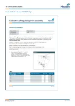
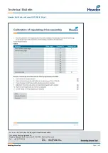
Checkpoint:
Note actual
theoretical minimum blade
angle and actual maximum
blade angle in document
V213351-9.
Any blade angle (maximum/minimum)
references in section 3;00 of the IOM manual
must be verified by comparing the blade
angle on the fan performance curve in
chapter 2:00 of the IOM manual. Any
deviations may be reported to Howden for
clarification.
Figure 2: Extract from drawing “Actuator Arrangement”
Figure 3: Fan Curve – find actual curve in Fan Manual “Performance Data”
Min blade angle = lowest mentioned angle + 1: (here 30+1=31)
Max blade angle = highest mentioned working point +1: (here 77+1=78)

