Technical Bulletin
Page 4 of 8
7.
Start the control oil unit and check that
the blade angle is 55°. If necessary,
the pull fork push rod length may be
adjusted until the blade angle is 55°
with oil pressure.
8.
Secure the crank in the vertical
position by means of the two socket
set screws.
Checkpoint:
Check vertical
position for the crank arm –
see Calibration of Regulating
Drive Assembly in verification
document V213351-9.
9.
Adjust the regulating drive external
graduated scale to 55° ± 0.5°,
corresponding to 55° measured on the
graduated scale of the blade
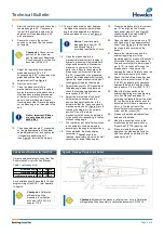
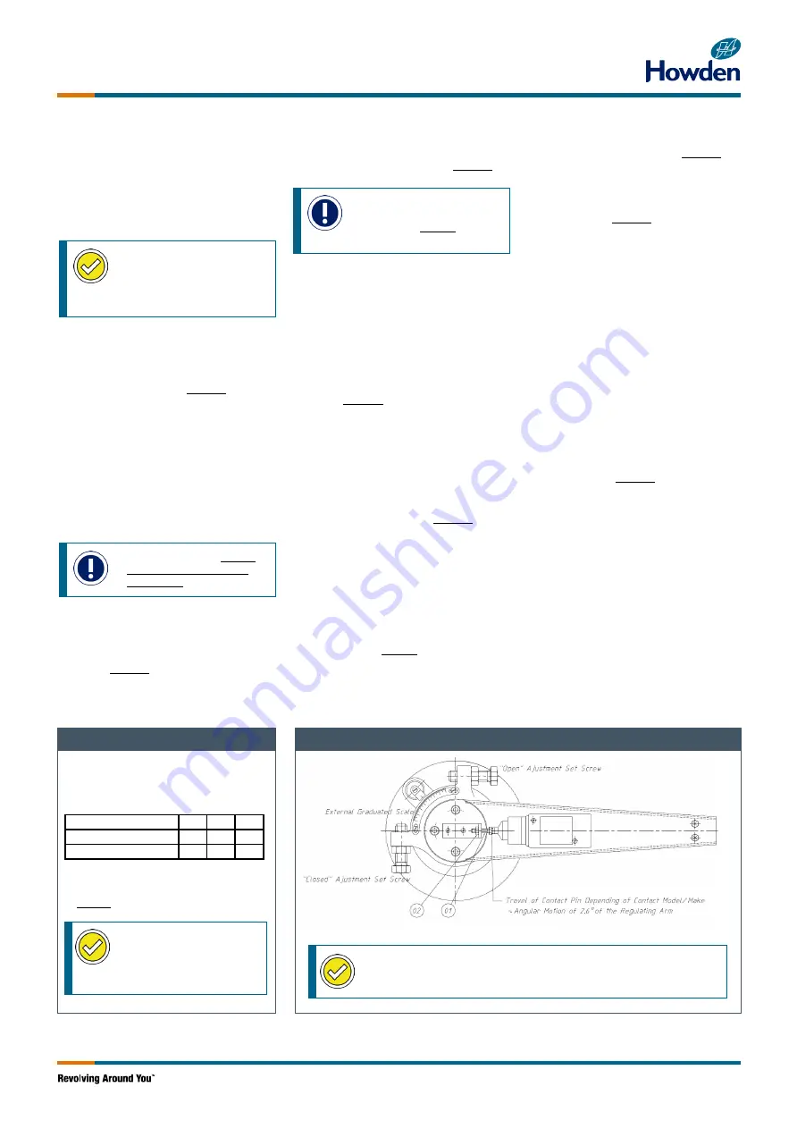
adjustment tool. See Figure 9.
10. Start control oil unit.
11. Close the blades carefully to
mechanical minimum limit, a spike in
hydraulic pressure will indicate a hard
stop has been reached. Mechanical
minimum is: contact of the internal
parts in hub or blades are close to
touching each other. Record the angle
on the blade angle tool mounted in the
hub.
Notice: Important: Blades
are not allowed to touch
each other.
12. Then open blade angle 2°, measured
on the graduated scale of the blade-
angle adjustment tool, and tighten the
“closed mechanical stop bolt”
(see Figure 9) towards the stop pin.
13. To avoid mechanical contact between
the blades the current minimum blade
angle must be adjusted to a distance
between blades
≥3
mm – see Figure 8.
Notice:
Correct example
blade angles in item 14) 19)
and 20) and Table 1
according to actual Fan Curve
14. Open the blades carefully to
mechanical maximum limit, a spike in
hydraulic pressure will indicate a hard
stop has been reached. Mechanical
maximum is: contact of the internal
parts in hub. Record the angle on the
blade angle tool mounted in the hub.
E.g. 78° measured on the graduated
scale of the blade adjustment tool and
tighten the “open mechanical stop bolt”
(see Figure 9) towards the stop pin.
15. Adjust blade angle to 55° measured at
the blade angle measuring tool and
check that external graduated scale
corresponds to 55° ± 0.5°.
16. Adjust the internal end of the travel
limit electronic switches and the
position feedback transmitter in the
actuator so that the “open and closed
mechanical stop bolts” (Figure 9) avoid
touching the stop pin in the extreme
position. One of the internal
mechanical switches can be adjusted
to the position corresponding to the fan
stall-cancelling angle.
17. The internal end of travel limit switches
in the actuator should be adjusted
according to the supplier's instructions.
18. When adjusted, the blade angles
(example) in Table 1 should be
reached. (recalculate mA value for stall
cancelling for actual blade angles).
19. Close the blades carefully to minimum
e.g. 31° and tighten the “closed
mechanical stop bolt” (see Figure 9)
slightly towards the stop pin and
secure with the locknut.
20. Open the blades to maximum e.g. 78°
and tighten the “open adjustment set
screw” (see Figure 9) slightly towards
the stop pin and secure with the
locknut.
21. Secure the internal crank and the
external regulating arm to the
regulating shaft by means of the socket
set screws. Dismount one screw at a
time and carefully drill a dimple (app 3
mm (0.12”)) in the shaft through the
threaded hole – take care not to
damage the thread. Carefully clean the
hole before remounting the screw.
22. Check that the friction brake disc and
friction disc are set at torque 10 Nm
(7.38 lbft) by adjusting the clearance
between the stop fork and the brake
disk to approx. 2-3 mm (0.08”-0.12”).
23. Mount the torque switch on the
external regulating arm (see drawing
no in Fan Manual) and adjust it
according to Figure 9. Adjust the screw
(01) so that the torque/limit switch is
activated, but still have a clearance of
X mm (Y”) to the bottom of the
torque/limit switch movement. Lock the
screw with the locknut (02).
24. Dismount the blade adjustment tool
and mount the blade.
25. Mount the inspection cover in the
impeller casing and seal with new
"Super Seal" (PTFE) packing cord.
26. If fans are installed for parallel
operation, the blade angle limits for
both fans should be adjusted to the
same value ± 0.5°.
Calculation of Set Point for Plant DCS
Figure 9: Placing of Torque Limit Switch
Correct angle according to curve from Fan
Performance Curve in the Fan Manual
Table 1 (reference only)
min blade angle 31
4,0 mA
max blade angle 78
20,0 mA
stall canceling angle
≤
42
7,7 mA
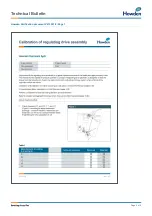
Any deviations should be noted for further
programming of the DCS – refer specially
Checkpoint:
Calibration
of Regulating Drive
Assembly in verification
document V213351-9 in
chapter 11.00.
Checkpoint:
Readjust the pressure relief valves – note in Calibration
of Regulating Drive Assembly in verification document V213351-9.

