14 I EN
fig. 5
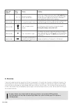
/ Face 2 of HOS regulation and connection diagram, description of HOS signalling
For proper function of the combustion control, the manual air control must always be fully opened.
Green
indicates:
normal function
of module U
Orange
indicates:
ventilation device
temporarily switched off
Red
indicates:
ventilation device permanently
switched off / module U
malfunction (error number
on the display)
Green
indicates: normal function
of modules A and W
Orange
indicates: door opened
Red
indicates: malfunction of module
A or W (error number on
the display), air supply flap is
opened, ciruclation pump is on
MODULE U
MODULE A (+ W)
Button for module U
restart
Button for pairing with
wireless display and for
restart (modules A and W)
Power adaptor of
control unit (24V)
Sensor for
pairing with
wireless display
Summary of Contents for HOS
Page 1: ...HOS User manual Bedienungsanleitung Uživatelský manuál ...
Page 2: ......
Page 3: ...EN HOS User manual 5 DE HOS Bedienungsanleitung 25 CZ HOS Uživatelský manuál 45 ...
Page 4: ......
Page 6: ......
Page 8: ......
Page 26: ......
Page 28: ......
Page 46: ......
Page 48: ......
Page 65: ......
Page 66: ......
Page 67: ......


